
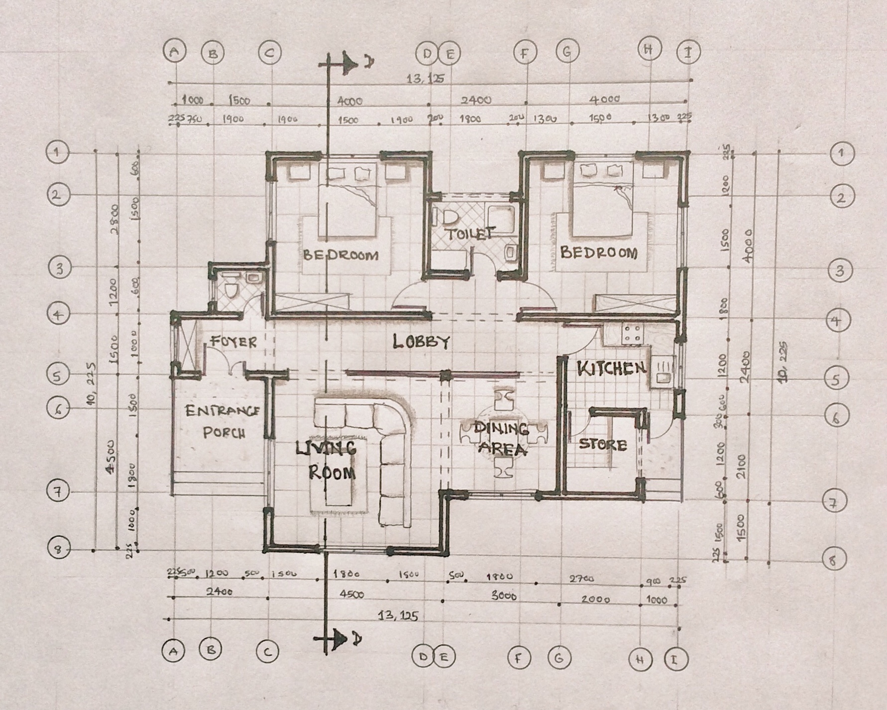
A floor plan is a scaled drawing of a building which shows the layout of spaces and how they interact. A floor plan can also be described as a horizontal section of a building, it cuts through the walls and openings within a building. Today we’re going to dive back into the Preliminary Design Stage to fully understand how floor plans are made. It isn’t just lines and rooms brought together; a lot of thought goes into the design of a floor plan.
Let’s start from Case Study and Literature Review. We have studied the proposed building type, conducted case studies, understood the brief and made decisions on the spaces/functions we want in our building.
We then selected the best possible site using a Site Selection Criteria and studied the surrounding environments using Site Maps.
Next, we did a Site Analysis. We have determined the micro and macro climate of the proposed site, the sun path, major wind directions, and have identified the best possible orientation strategies to be adopted by the building to optimize natural lighting and ventilation.
We then used Zoning to identify which spaces belong in which zone (noisy/quiet zones, private/public zones, accessible zones and secure zones)
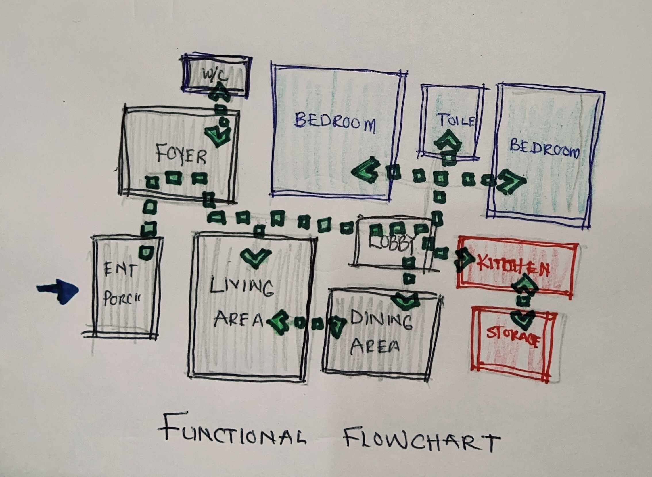
Bubble Diagrams helped us zone the spaces/functions of the proposed design and understand how each zone interacts with one another and how they are connected, while Functional Flowcharts helped us connect spaces and functions to each other to bring about functionality and circulation routes within the building.
Finally, we conducted a Space Analysis to understand the space needed to make the proposed spaces/functions functional and comfortable for the user.
Now, how do all these steps play a role in creating a floor plan? The answer is right here in this post.
Generating a Floor Plan from Your Design Preliminaries
Let’s take a look at our functional flowchart. We have the spaces we need for the design and we know how the connect on one another.
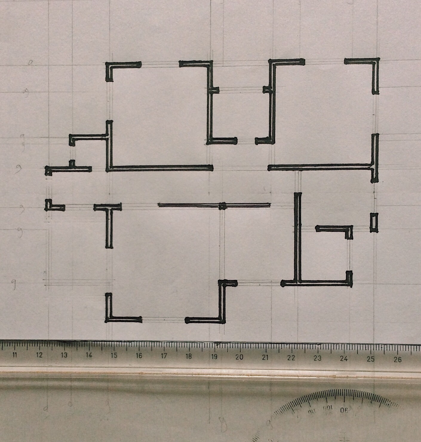
The next step would be assigning dimensions to these spaces. The dimensions we will be using come from the space analysis conducted. Being it a sketch, the shape of the floor plan may not be the final outcome after assigning dimensions. One way to sketch to scale is by using sketchpads that have grids or dots. You can use the grids as a guide to help you sketch floor plans to scale.

There might be a variation of walls used in the design. There might be masonry walls, curtain walls, partition walls, etc. These walls all have various thicknesses and styles which represent them. Add this to your sketch to start understanding the final outcome.
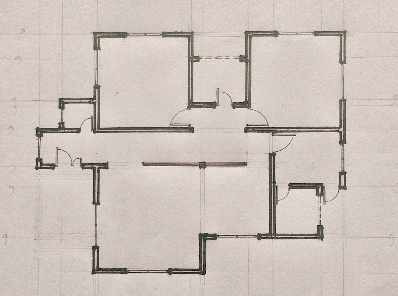
We then add openings to the sketch. We determine the positions of doors and windows. It is necessary to research the type of windows and doors you want to use in your design. Ensure you achieve cross ventilation when positioning windows, and doors are often positioned to rest on walls.
Next, we determine the position of fixtures and furniture. Fixtures are permanent pieces of furniture that can not be moved like sinks, toilet seats, cabinets, stairs. It is important to indicate the position of each fixture using its appropriate symbol.
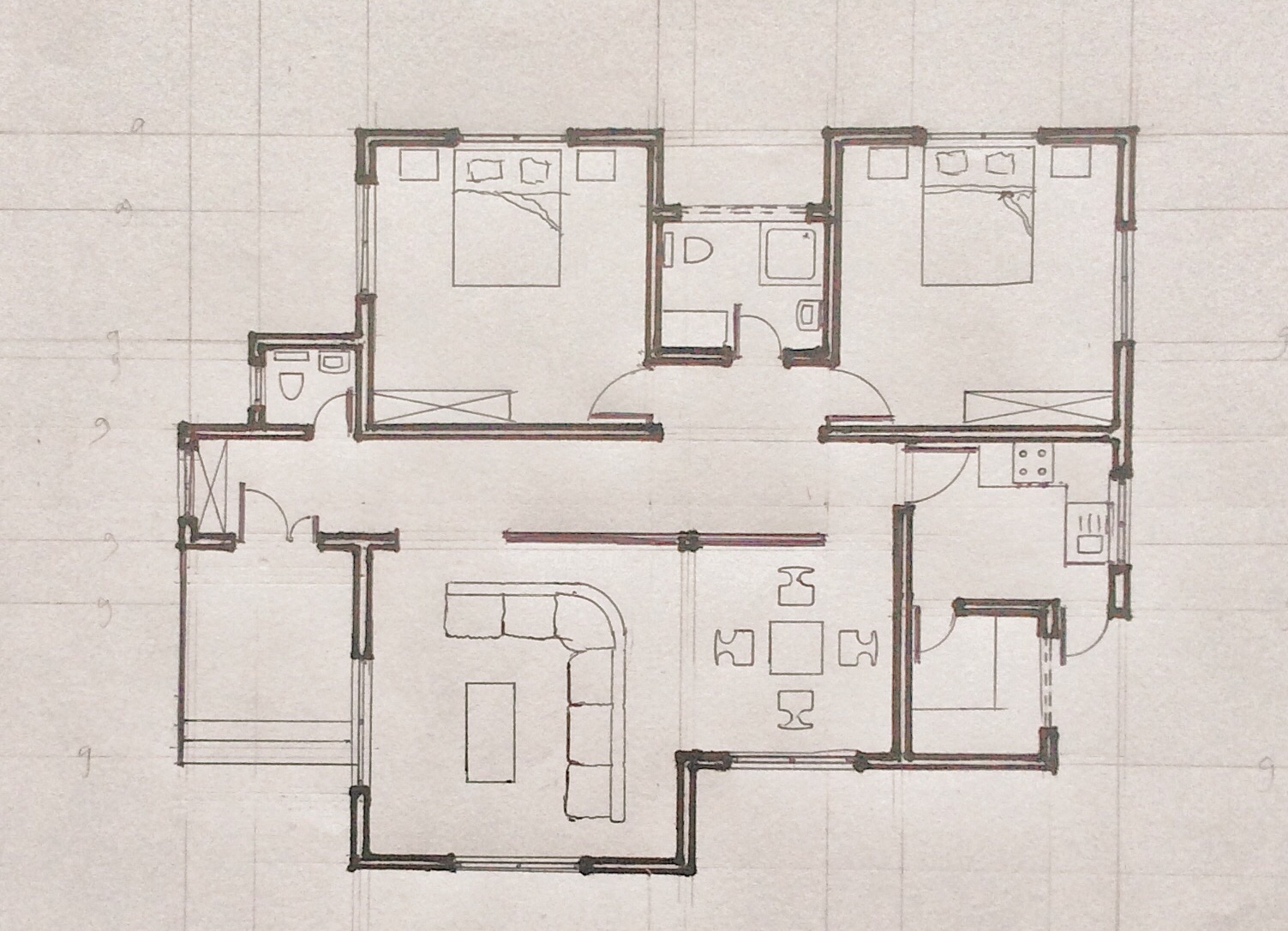
Finally, we add other details like hidden objects, floor finishing, labels, etc. These give more details to the floor plan and help others understand each aspect of the floor plan.
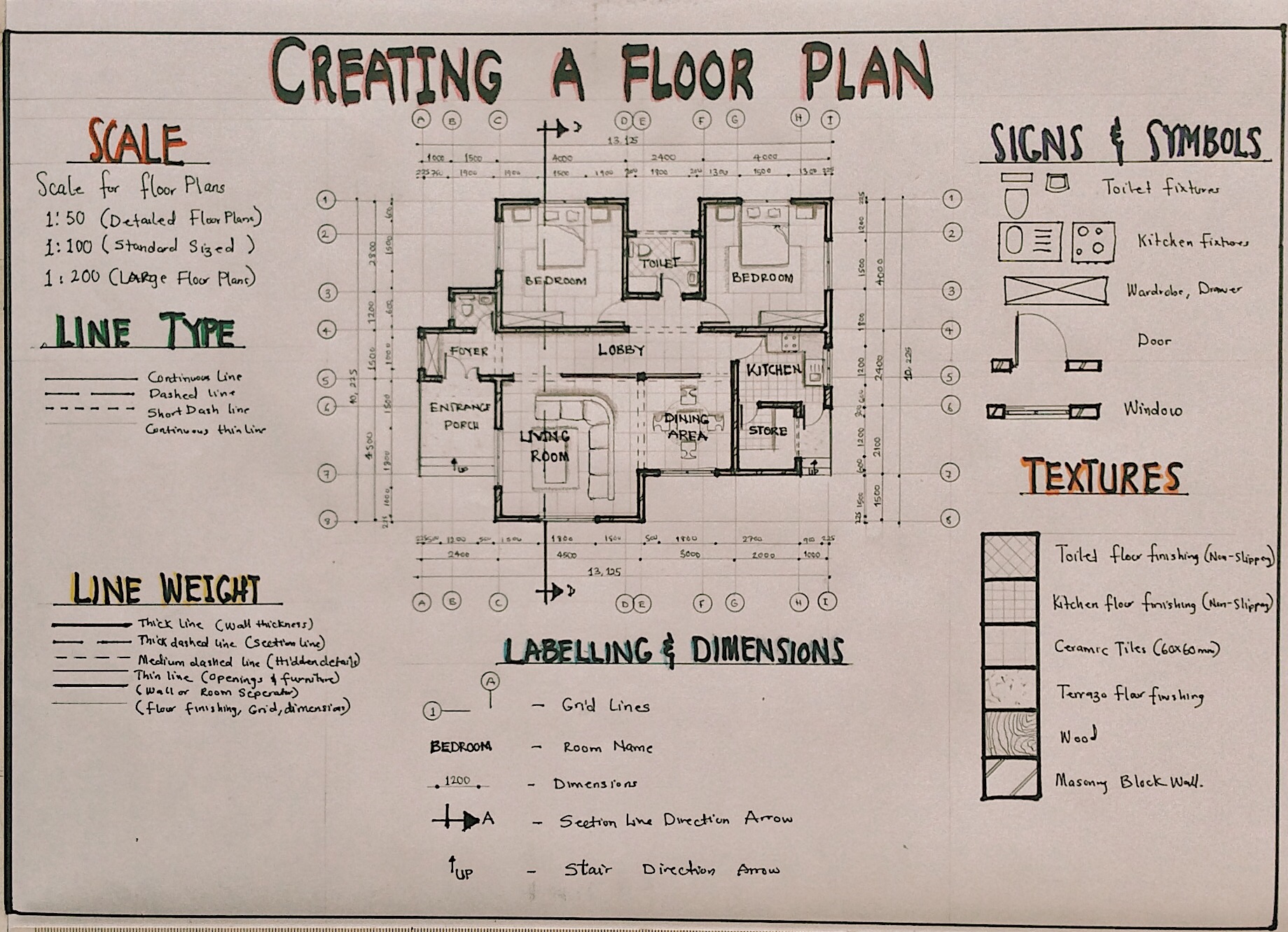
Floor Plan Graphics
To draw a floor plan, there are certain graphical and design elements you need to consider.
- Scale
The scale used in drawing a floor plan depends on the size of the floor plan, the available drawing space, and the level of detail to be shown. Generally, we use scale 1:100 to draw a floor plan. For large floor plans, the scale moves to 1:200. To show more details on a floor plan, we use scale 1:50 (scale is in millimeters).
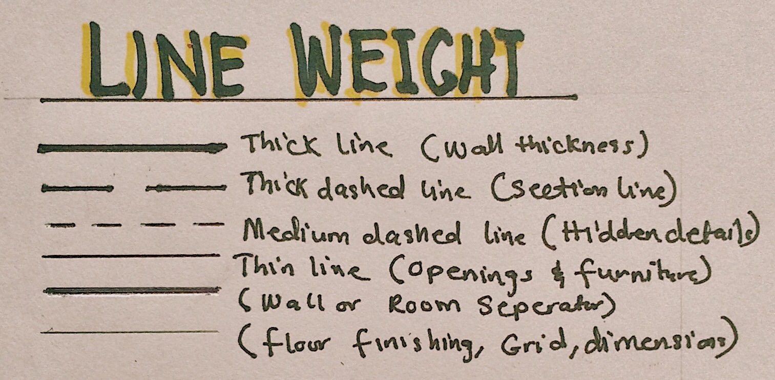
- Line weight
There are a lot of line weights displayed in a floor plan. The most obvious one being wall thickness. It is the thickest of them all. Openings and fixtures are drawn in a medium thickness while floor finishing and dimensions are drawn with thin lines.
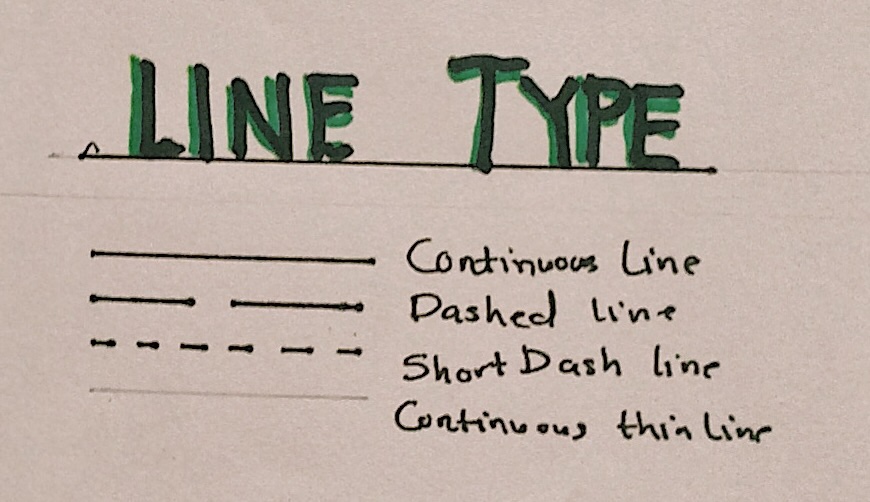
- Line type
Walls, openings, fixtures, furniture are drawn using continuous lines. The section line is a thick broken line, while hidden objects are drawn with short dashes. Grid lines are thin chained lines.
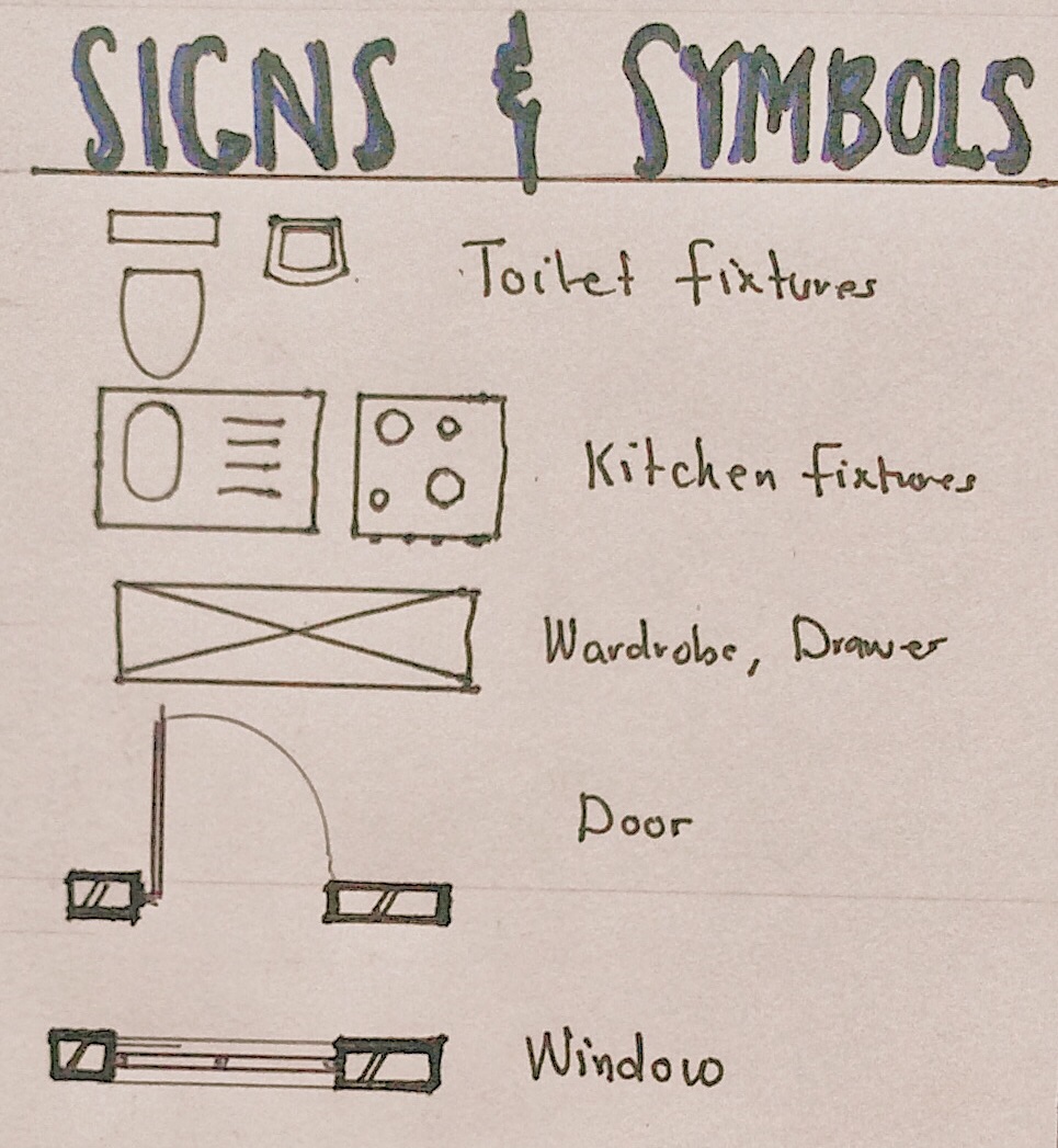
- Signs and symbols
Floor plans have a mixture of many signs and symbols. Below is a diagram of some signs and symbols used in a floor plan:
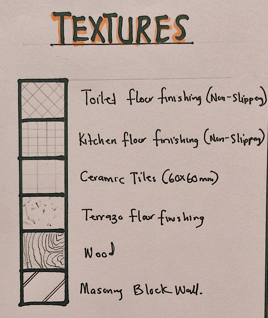
- Textures
Here are some textures we adopt in designing floor plans:
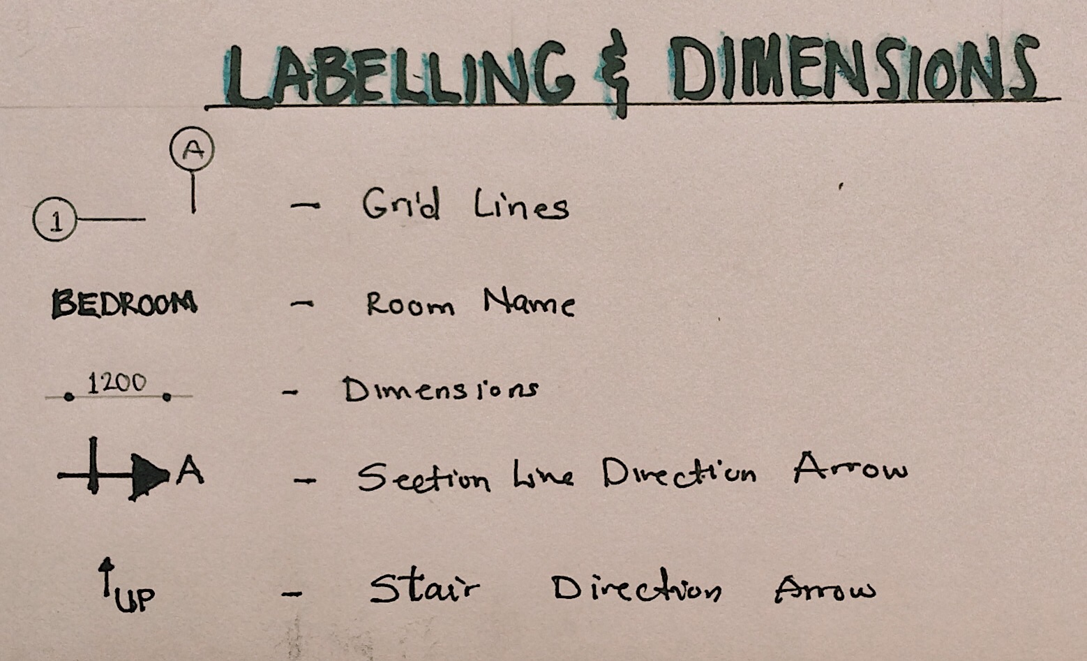
- Labelling and Dimensions
Labelling spaces, indicating stair movement, adding grid lines and adding dimensions to the floor plan are basically the final touches. They convey more information that help you communicate certain details.
Floor plans are usually the starting point for other drawings; therefore, it is important to get it done right. Stay tuned to read about other drawings in future posts. Thank you for reading!

A very interesting piece….keep it up!!
LikeLiked by 1 person
Thank you!
LikeLike
This is quite encouraging. Thank you for sharing and demonstrating that good things can come from within. I like the simplicity and use of language that is contextual
LikeLike
Thank you for kind words! I really appreciate it.
LikeLike
Thank you, it’s great work you’re doing here!
LikeLiked by 1 person
Thank you Sadiq.
LikeLike
Wonderful Malama Mariya 👏🏿.
I’m always intrigued by your unwavering enthusiasm. We’ve gained alot from your posts.
I do love the way you linked the preliminary drawings to the actual proposed. From my experience, I’ve noticed a lack of coherence between the two in the designs students produce in school. I hope they’ll learn from it.
LikeLiked by 1 person
Thank you Ahmad! Hopefully we’ll see a change very soon.
LikeLike
*actual PROPOSAL
LikeLike
Keep up the good work twinnie
LikeLiked by 1 person
Thank you!
LikeLike
Wow,
Alhamdulillah, Mariya keep it up. Allah will bless your projects
LikeLiked by 2 people
My goodness. Thank you very very much. Words won’t explain how grateful I am for the knowledge I gain from your blog
LikeLiked by 1 person
Thank you Charles.
LikeLiked by 1 person
I know you must be very very busy☺ We anticipate more episodes on the series please
LikeLike