A site plan is a visual representation of a building or a building complex describing its location and orientation in a plot of land and in relation to its context. A site plan is drawn in a two-dimensional view, and it is a view from the top, looking down onto the site. Site plans are developed after a thorough Site Analysis has been conducted. They show existing and proposed features of the design. Existing features may be the site topography, vegetation, existing infrastructure or buildings (those that are to be retained in the design). Proposed features include the proposed building, proposed landscaping or infrastructure.

Site plans are designed to describe the following features:
- Property lines: these are the legally recorded boundaries of the site.
- Topography: contour lines on the site plan describe the terrain of the site.
- Natural site features: these can include trees, landscaping, water bodies.
- Existing or proposed site constructions: these can be walkways, roadways, landscaping.
- Existing or proposed site utilities: these might be drainage facilities, plumbing pipes, gas lines, etc.
- Pedestrian and vehicular entry points and paths.
- Legal constraints: such as setbacks, rights-of-way, etc.
Site Plan Graphics
To draw a site plan, there are certain graphical and design elements you need to consider.
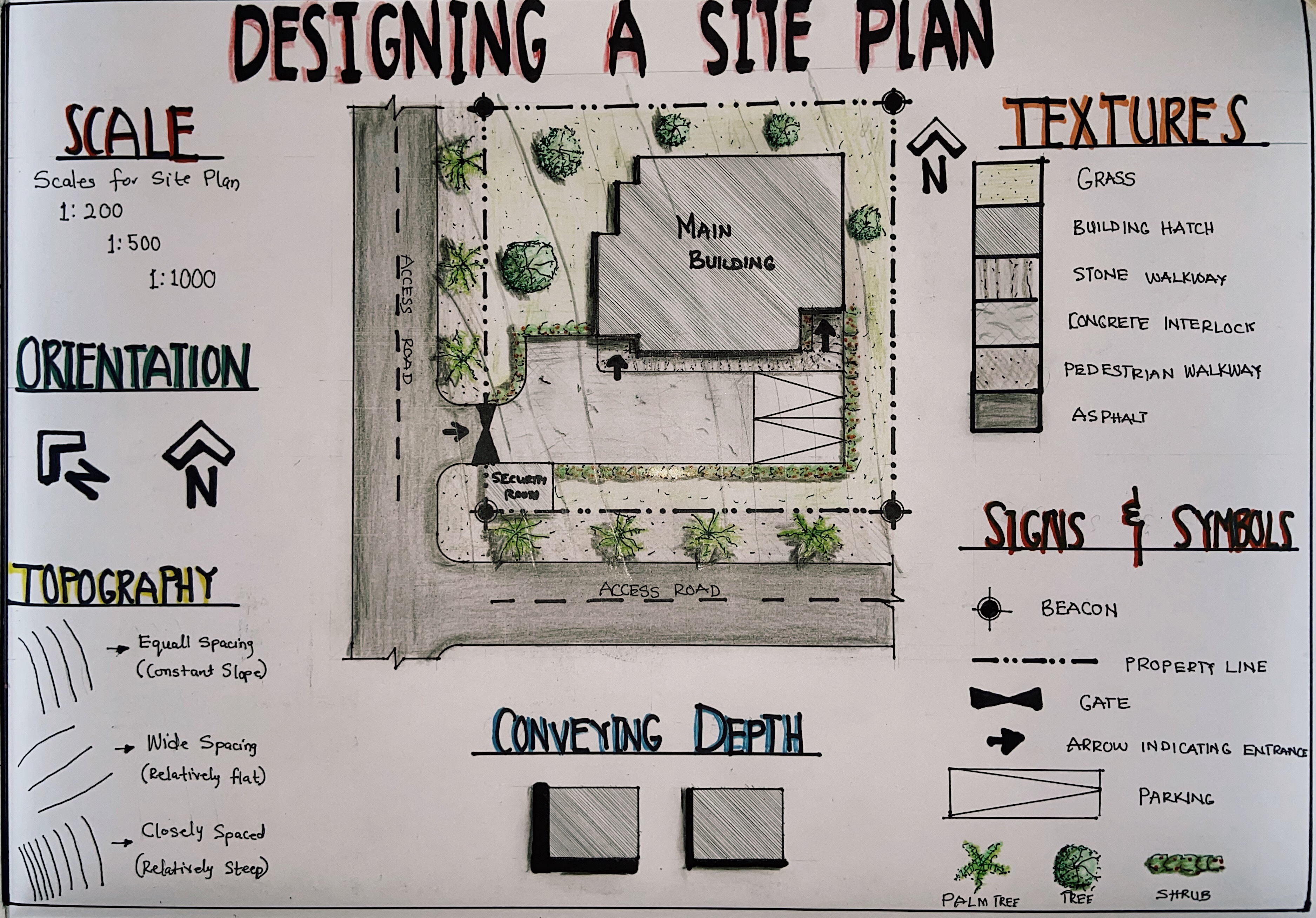
- Scale
The physical size of a site is too large to fit into drawing sheets. This is where scale comes into play. You can adopt appropriate scales depending on the available drawing space and the level of detail you want to show. In architecture, we have specific scales we use for each type of drawing. The ideal scales for a site plan include 1:200, 1:500, or even 1:1000 (scale in millimeters). For a detailed site plan, you can adopt 1:200, while you can use 1:500 or 1:1000 for large site plans that do not require much details.

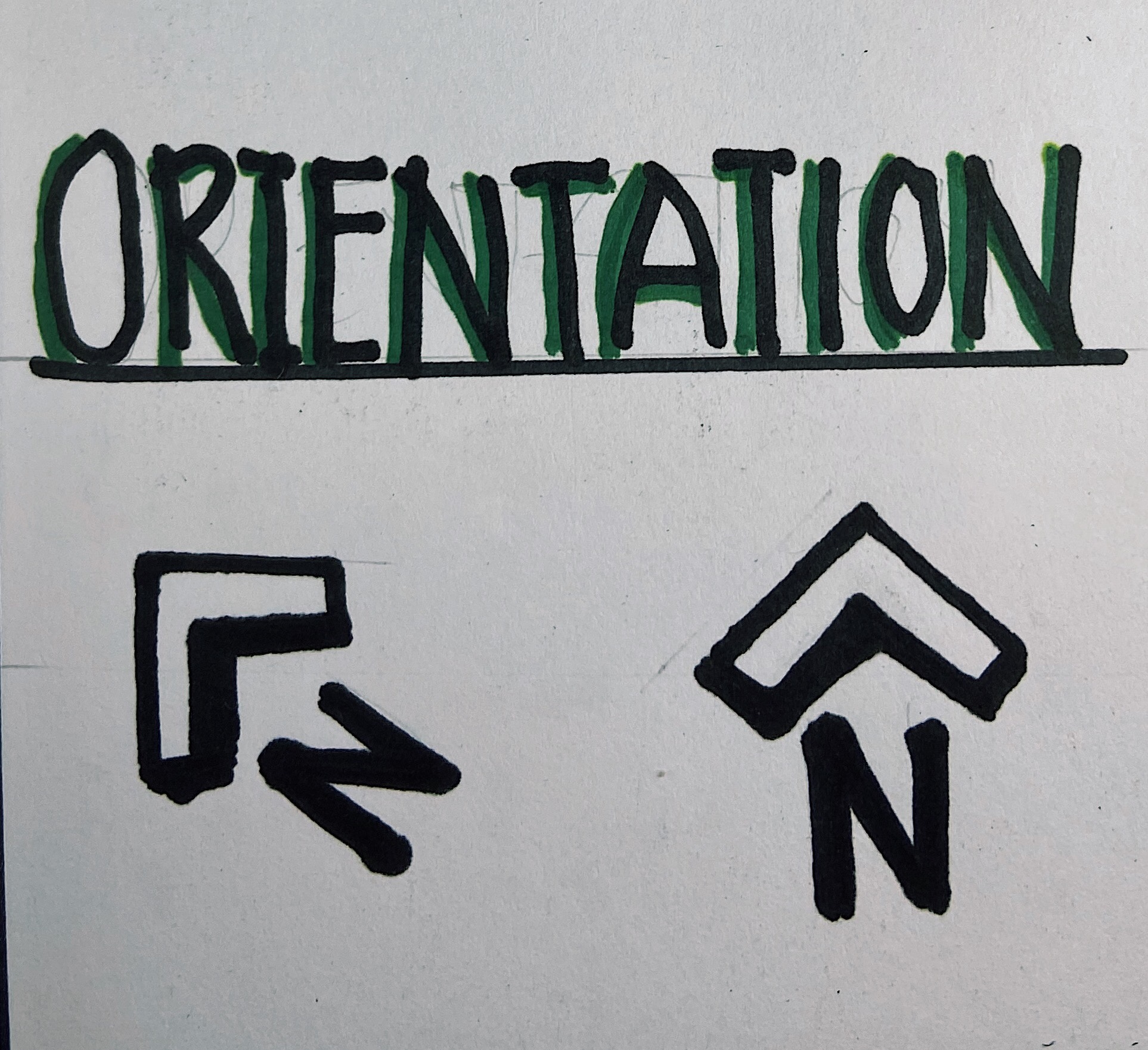
- Orientation
There has always been a huge debate as to how a site plan should be oriented. Some schools of architecture suggest that the site plan should be oriented the same way the floor plans have been drawn to maintain a relationship between the site plan and the floor plan, while other schools suggest that the North Arrow determines the orientation of the site plan on paper. The North Arrow is drawn in the top right-hand corner of the paper and the site plan is drawn in reference to it. Find out which style your school uses and adopt that in your design.
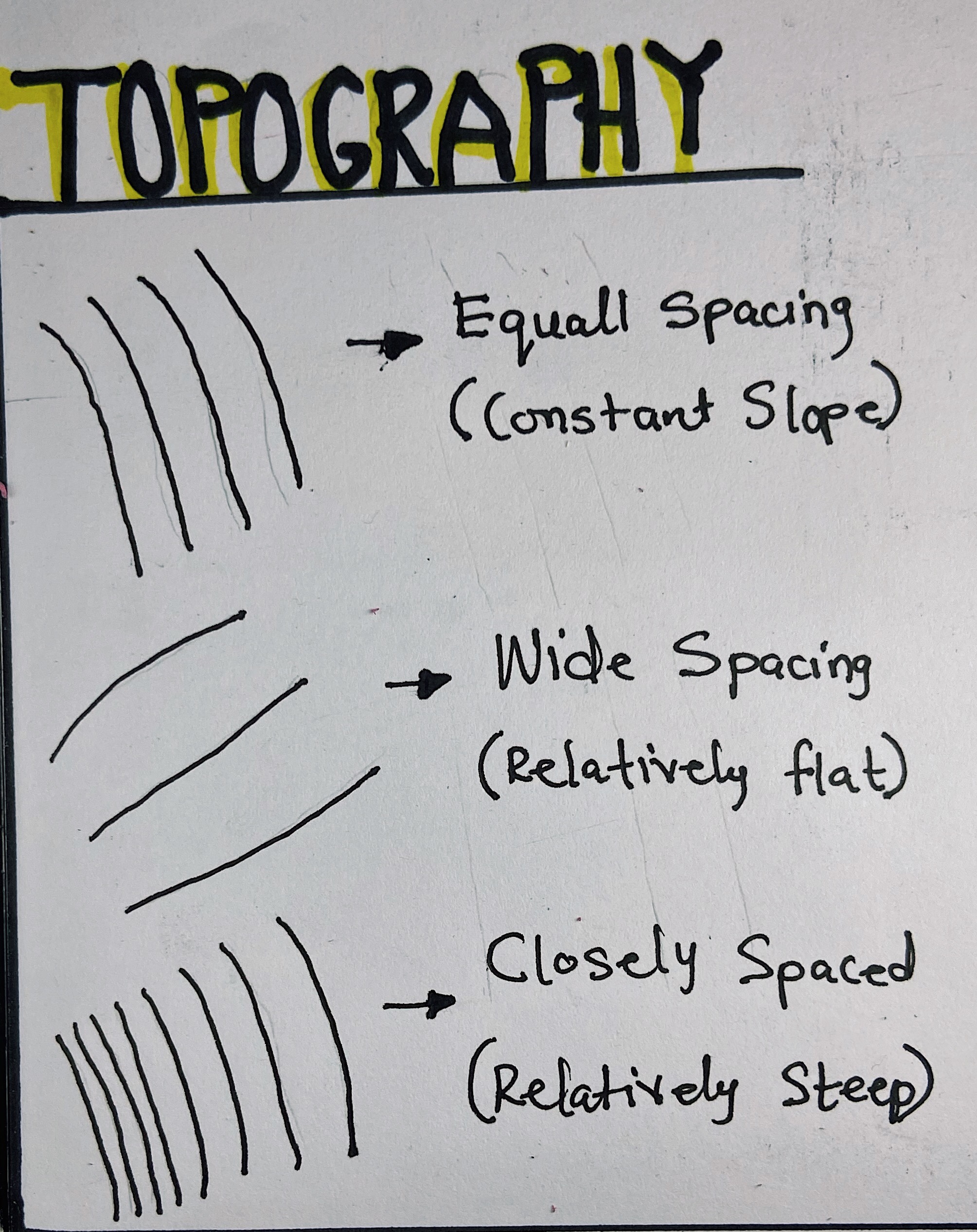
- Topography
Contour lines are the graphic convention we use to convey the terrain of a site. Contour interval is determined by the scale of a drawing, the size of the site, and the nature of the topography. The horizontal distances between contour lines in a site plan are a function of the slope of the ground surface. We can determine the topographical nature of a site by reading this horizontal spacing. Contours spaced far apart indicate a relatively flat or gently sloping surface. Equally spaced contours indicate a constant slope. Closely spaced contours indicate a relatively steep rise in elevation.
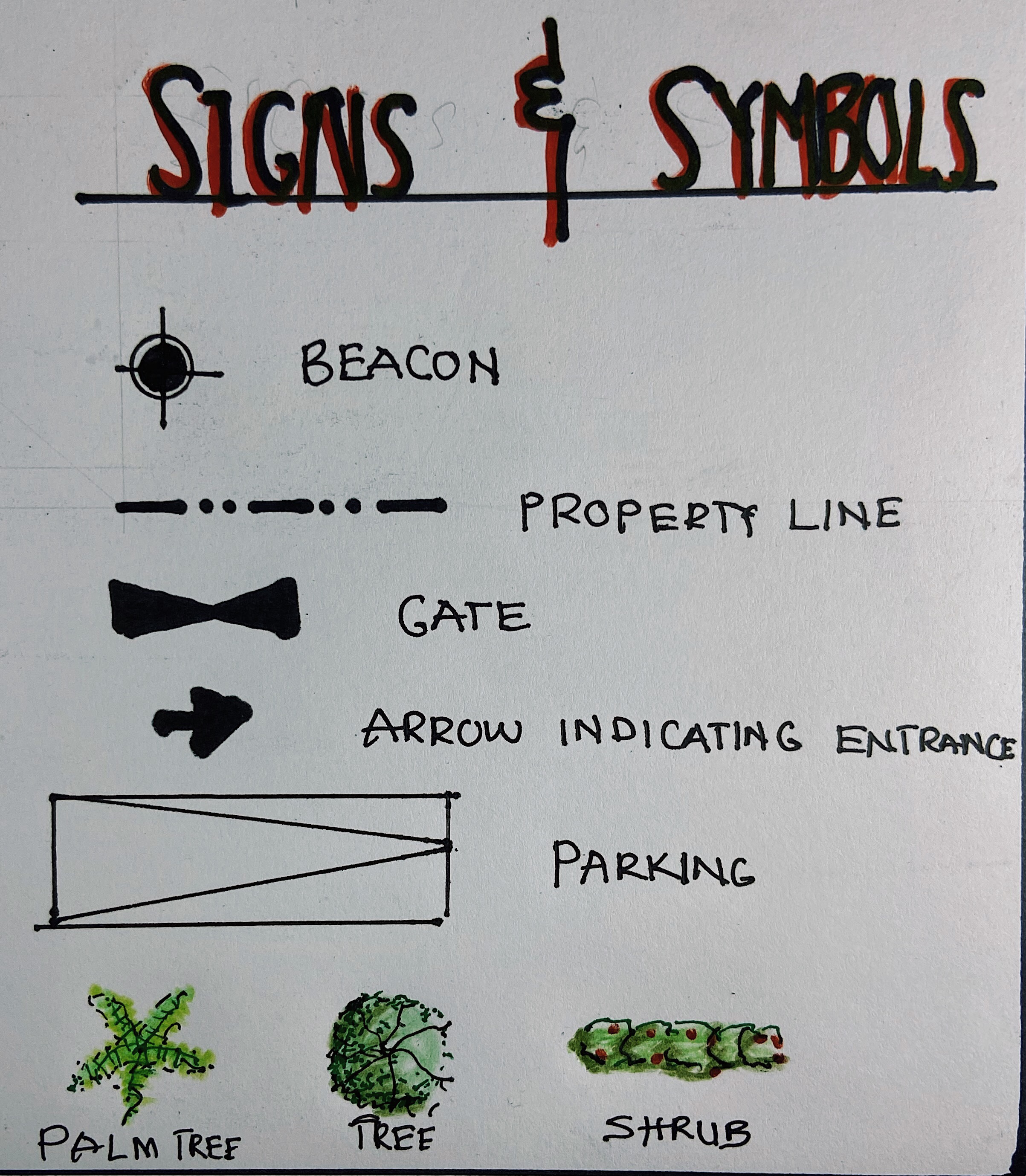
- Sign and Symbols
Different signs and symbols are used in the design of a site plan. A mixture of line types and line weights helps represent each and every feature of the site plan, for example, property line is represented by a broken line consisting of relatively long segments separated by two short dashes or dots, contour lines are represented by thin continuous lines, hidden elements like underground tanks or septic tanks are represented by thin dashed lines. There are also symbols that indicate orientation (North Arrow), street signage, flow of traffic, parking, landscaping elements, etc.
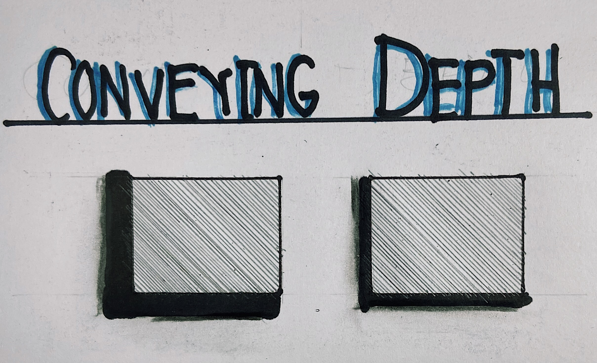
- Conveying depth
This can be achieved through shading. Casting shadows helps convey the height of site elements in relation to the site. This gives a three-dimensional illusion to the drawing if done properly.
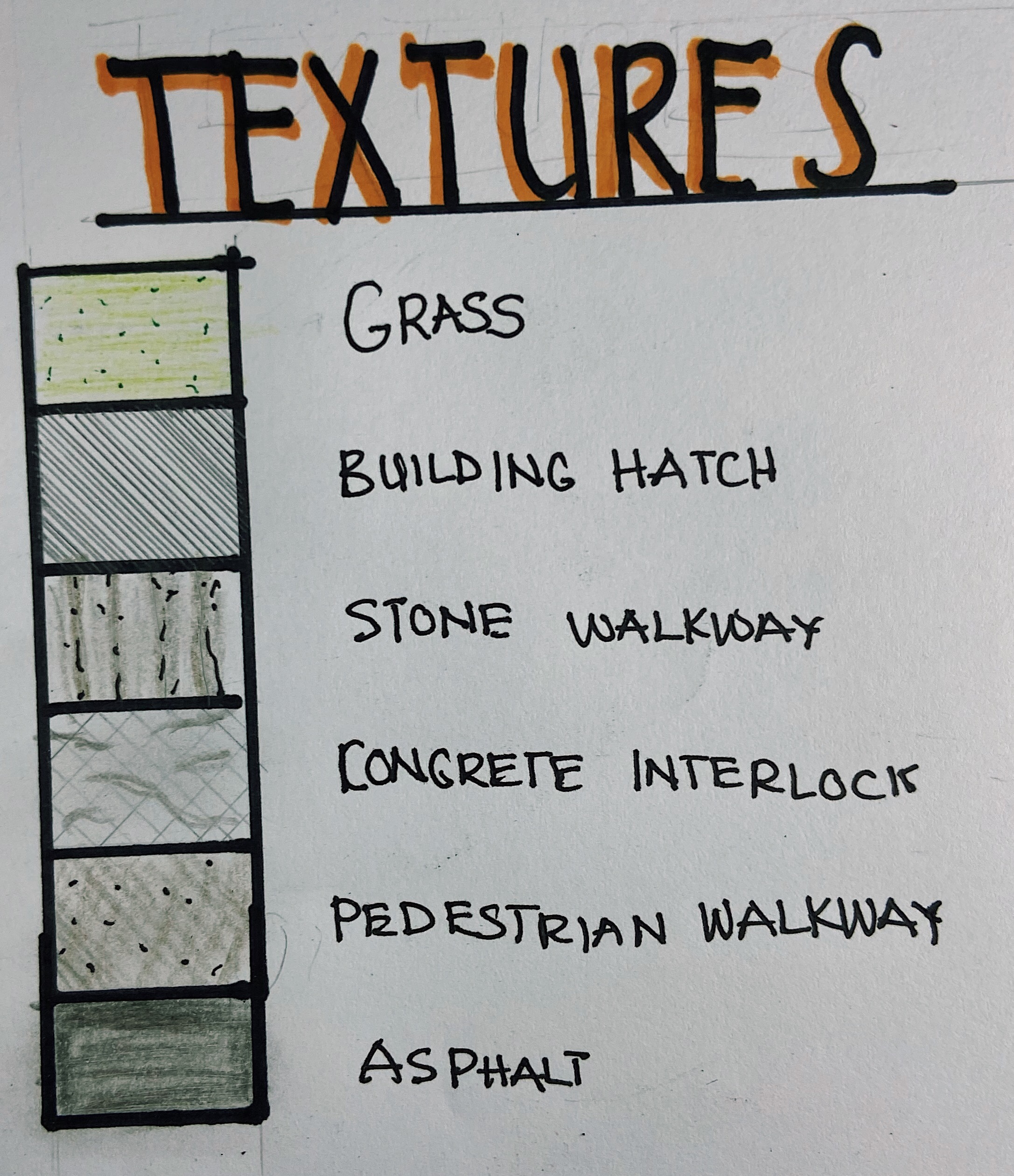
- Textures
It is important to represent textures on a site plan. This gives it a more realistic touch. Textures usually found in a site plan include grass, trees, stone walkways, interlocks, asphalt, roofing materials, water bodies, etc. You can always add color to your drawings to give it more meaning.
Applying all these elements together will help you produce a functional and aesthetic site plan. It should be like you are telling the story of the site and the building. For other people to understand your design, you must tell the whole story. The more details you describe on your site plan, the less room you leave for interpretation.
What guidelines does your school have regarding site plans? Do you rotate your site plan, or rotate your north arrow? Do you show the roof of your building or do you simply hatch the building area? Comment down below and stay tuned for more posts!
Great! A remarkable shift towards improving architectural education from Quifdiyyah Aminu Kabir. Kudos
Well done job
Good job. Keep it up
Wow. This is so nice thanks
Awesome job, well done
architect remain blessed
great job. thanks