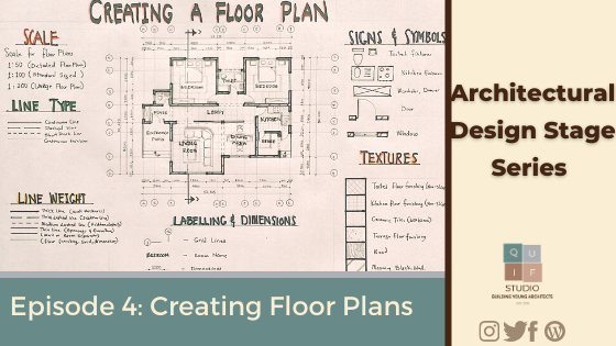
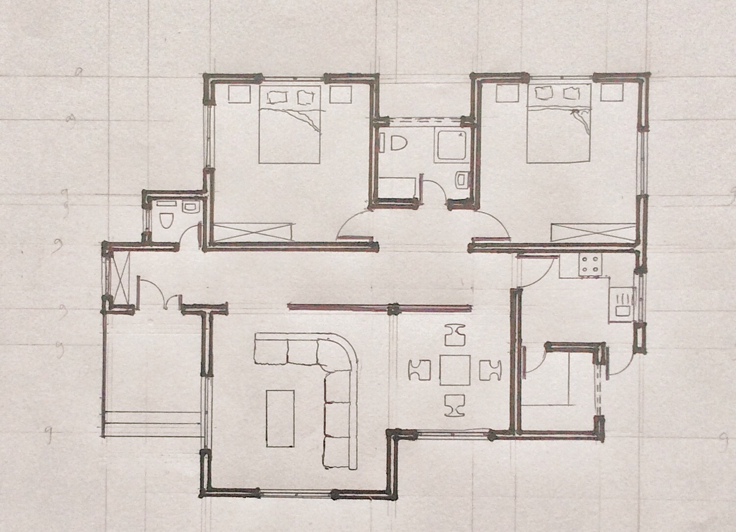
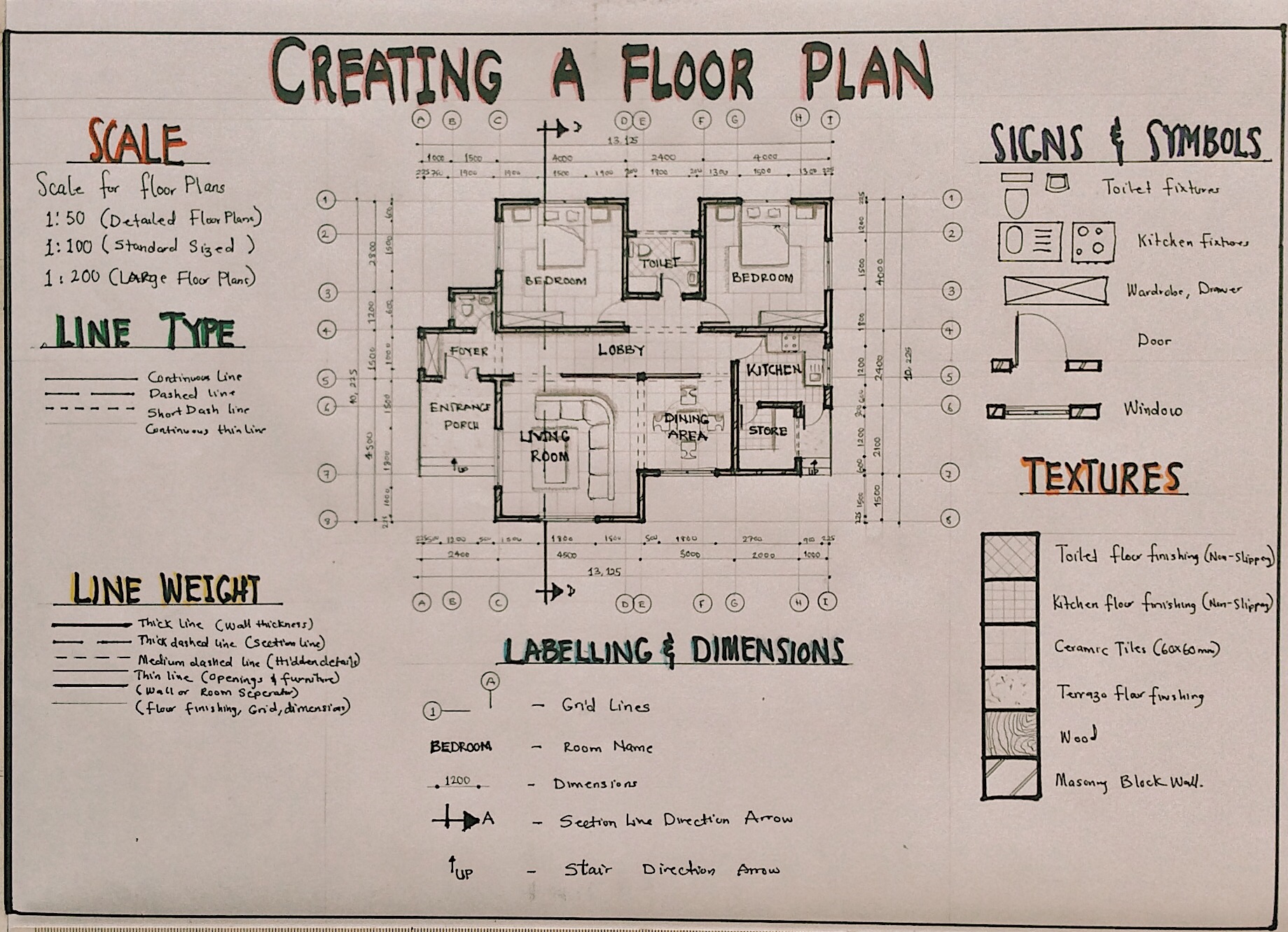
The working drawing of a floor plan gives a lot of information which is vital to the construction process of buildings. It tells us the sizes and dimensions of all design elements of the plan which ranges from the walls, openings, fixtures and staircases. It also tells us the type of materials and finishes used as well as other graphical details about the building. In this post, you will learn about all the required information for the working drawing of a floor plan.
Dimensions and Sizes
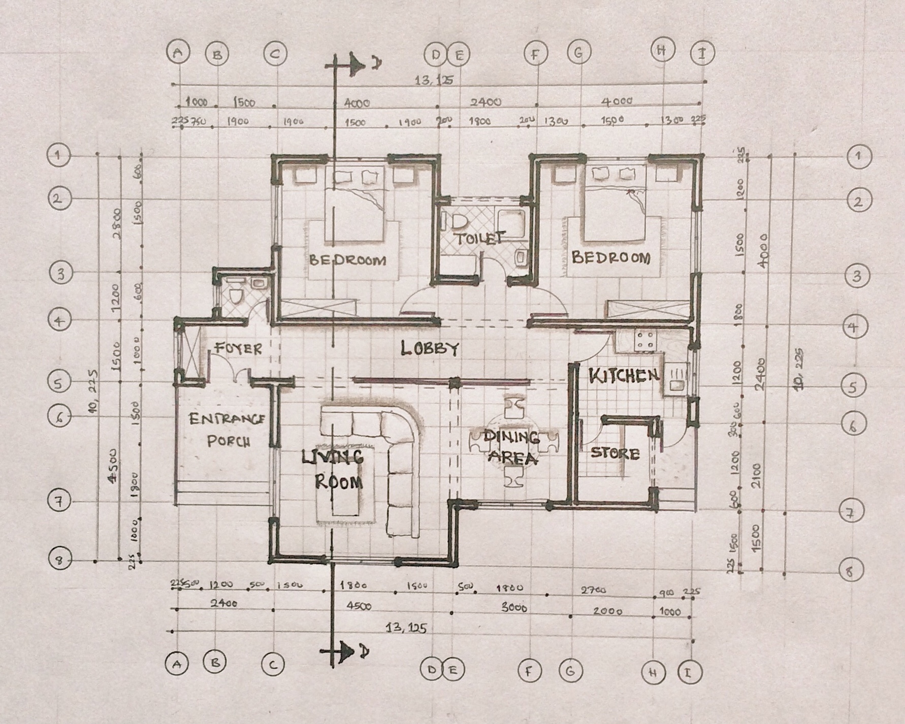
The dimensions and sizes of each building element is required. This includes the following:
- Overall dimension of building on all sides.
- Internal dimension of all rooms, corridors, verandas etc.
- Internal dimensions of all recesses, wardrobes, cupboards, counters etc.
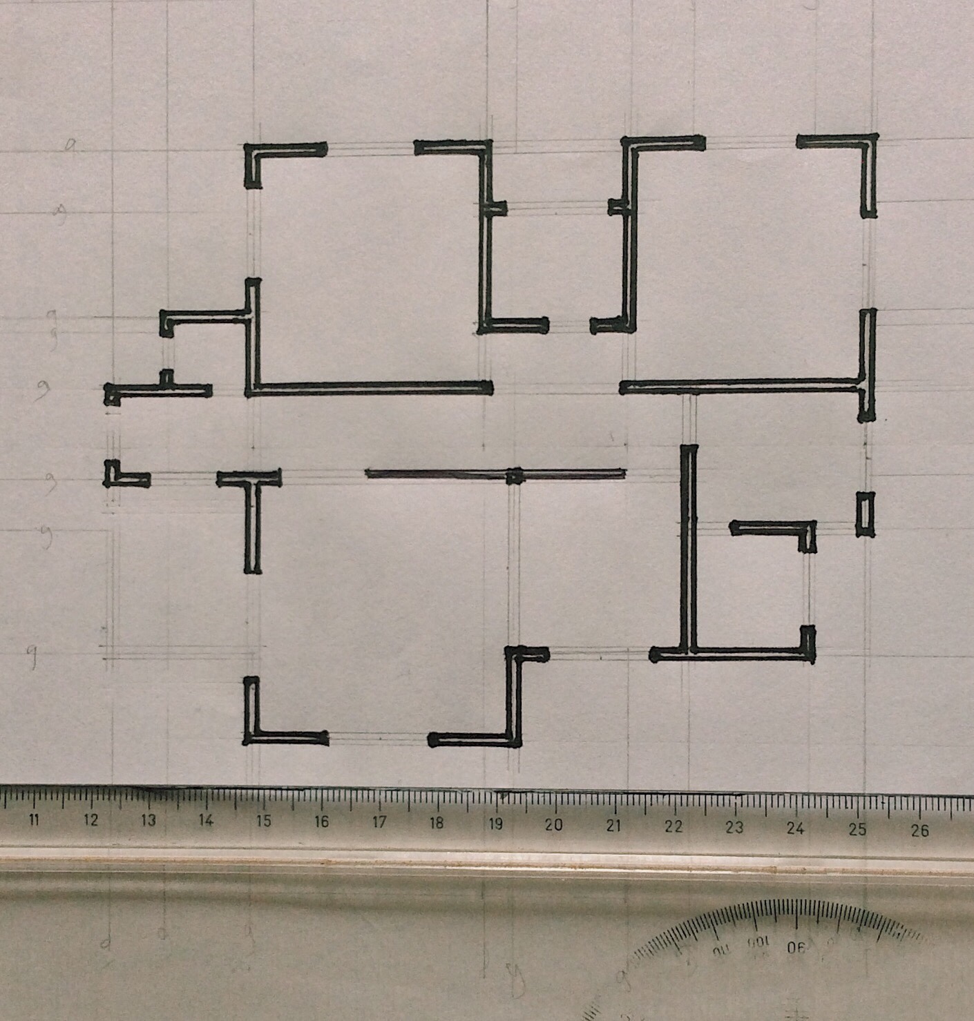
- Thickness of all walls, partitions, etc.
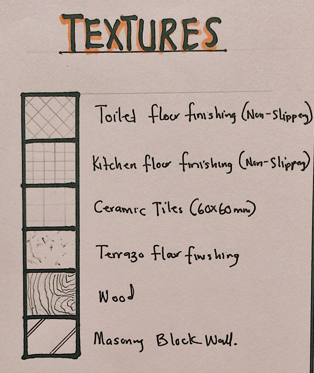
Materials, Finishing and Levels
The following information must be indicated in the drawing:
- Indicate type of walls, i.e., block wall, brick wall, stone or timber etc.
- Indicate internal and external finishing schedules of the walls of all rooms.
- Floor finishes of all spaces including veranda, wardrobe etc.
- Floor levels of all places relative to a fixed datum.
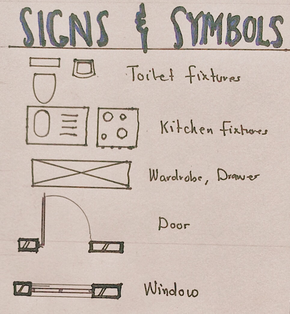
Openings and Fixtures
The following information on openings and fixtures must be indicated in the drawing:
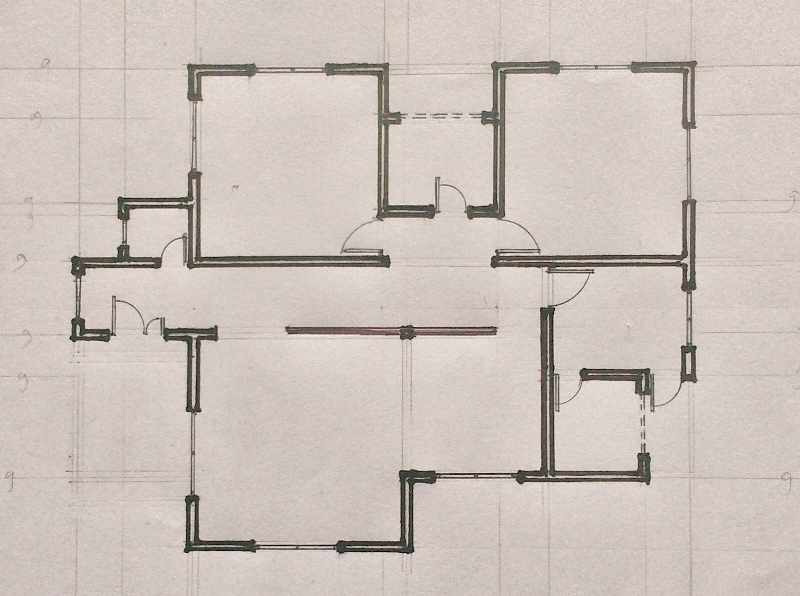
- Indicate width of all doors, windows and other openings.
- Indicate swings of all doors.
- Number all doors, windows and curtain walling etc.
- Locate all sanitary fittings and label them appropriately.
- Indicate position of all fixtures and label them appropriately.
Staircases and Ramps
The following information must be indicated in the drawing:
- Width of all treads at staircases and all level changes.
- Number of all risers at staircases and all level changes.
- Indicate direction of flight at all staircases and all level changes.
- Indicate direction of the slope and the slope degrees/percentage.
- Indicate width of slope and all level changes.
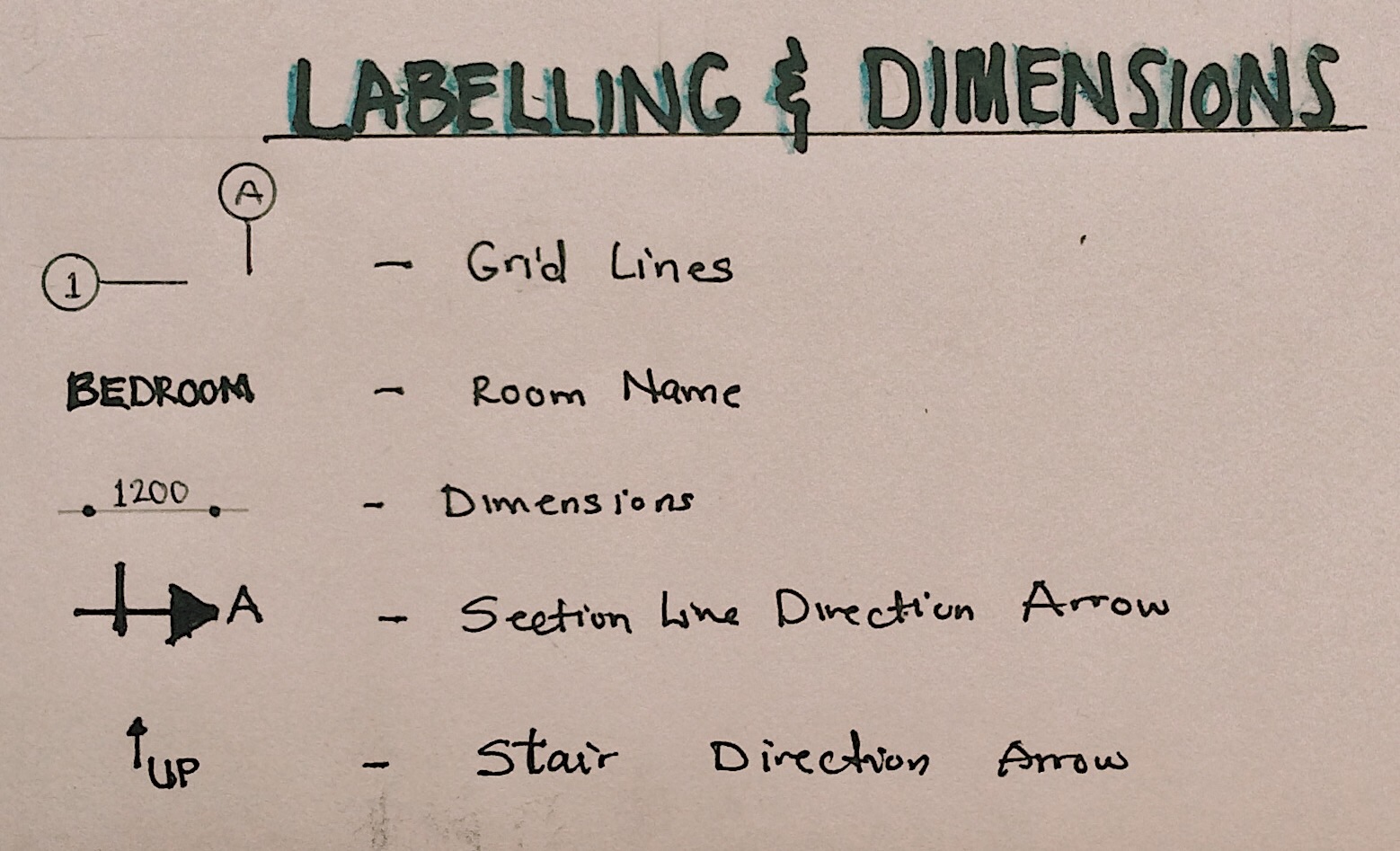
Annotations and Additional Information
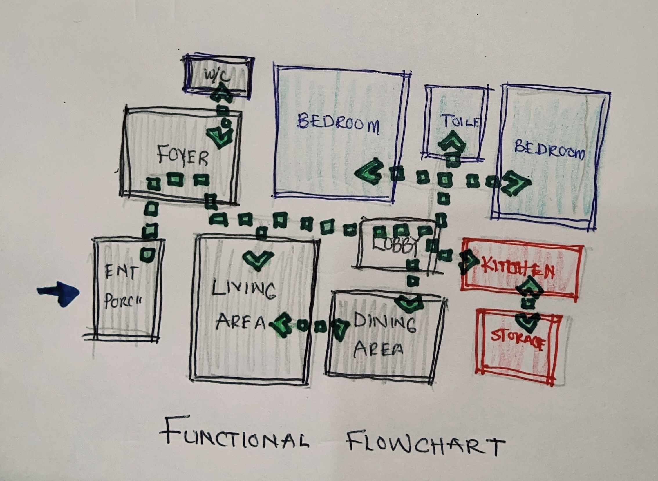
- Indicate function of all rooms including semi-open spaces.
- Indicate all section lines.
- Indicate in broken lines extent of roof overhang, cantilevers etc.
- Provide grid lines (both ways).
- Indicate areas (if any) where further details are provided in subsequent drawings or by other consultants or manufacturers.
Graphics of Floor Plan Working Drawing
- Scale
The size of a floor plan in working drawings should be large enough to expose details of the drawing. The scale depends on the size of the building. 1:50 can be adopted for relatively smaller floor plans, while 1:100 can be adopted for larger buildings. However, some parts of the floor plan can be blown out with a bigger scale to reveal more information.
- Dimensions
Dimensions are a vital part of working drawings. All parts of the drawing should be fully dimensioned; however, repetition should be avoided to prevent confusion. Dimensions should be accurate and legible.
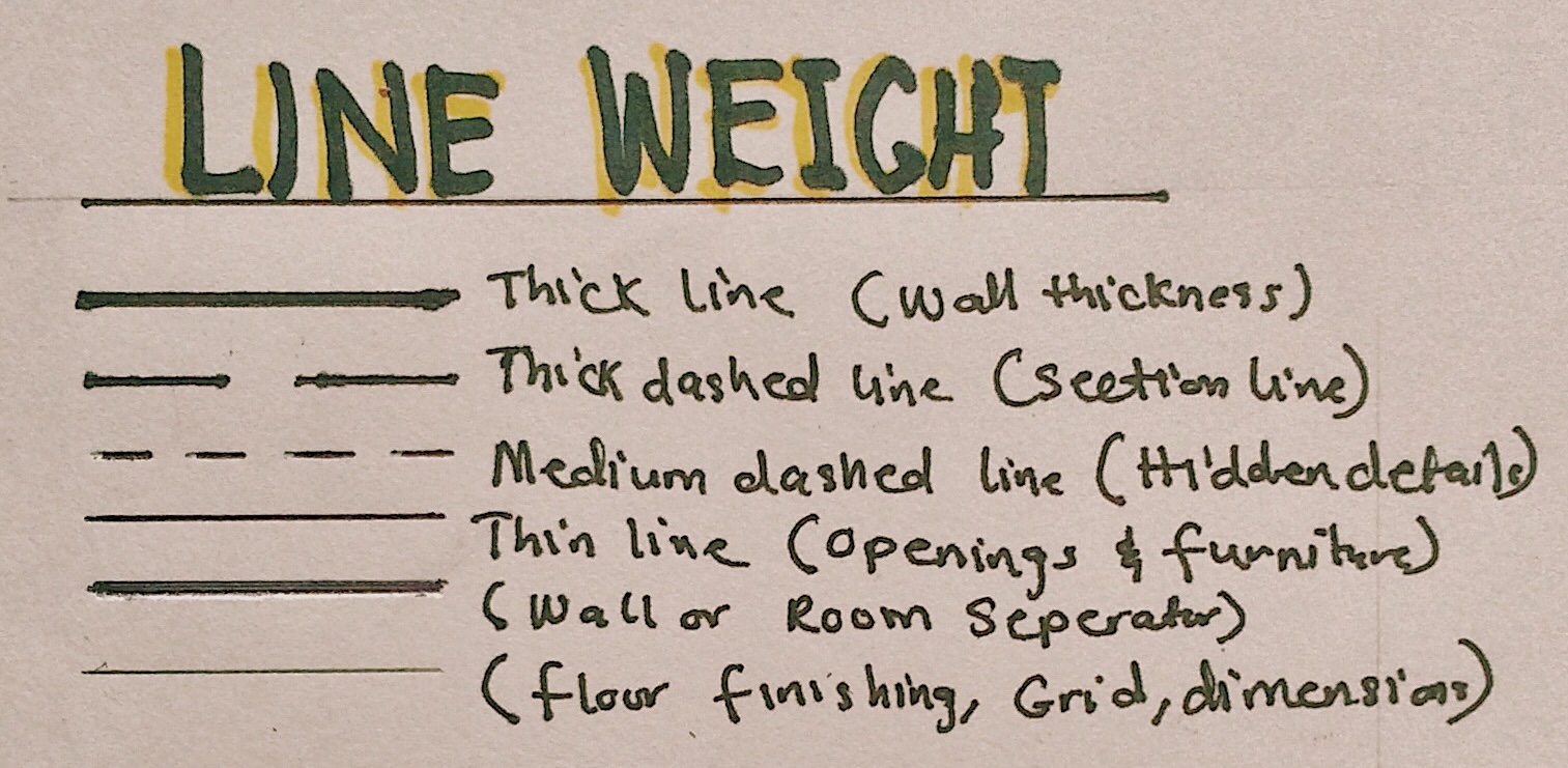
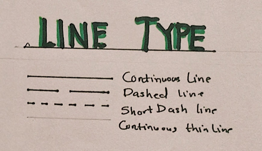
- Symbols and Annotations
Working drawings are technical drawings therefore having many symbols and annotations for graphical representations. All symbols and annotations should be accurate and easy to understand by all members of the construction team. Here are some symbols and annotations used in floor plan working drawings:

- Specifications
Materials and finishing should be fully specified in the working drawing. This information can be provided in the drawing, or in the specification document of the project.
In conclusion, drawing a floor plan is a fundamental skill in architecture and design. It serves as the foundation for visualizing and communicating the spatial layout of a building. The working drawings and specifications provided in a floor plan can create a detailed and accurate guideline that effectively represents your design intent and help bring the design to reality in a seamless manner. To have access to a complete checklist of information to be provided, you can click the download button below.