How do we represent our designs as architects? We do so through either 2D or 3D drawings, but the bigger question is how do we communicate? How can a person you’ve never met understand your drawings without your presence? The answer is simple, through graphical communication. Drawings are made up of different elements such as lines, shapes, textures which give meaning to the drawing. We communicate through those elements, which helps other architects, or other professionals from our industry such as engineers, builders and the rest understand our designs.
In this post, we will be discussing the following graphical elements that make up architectural drawings
- Lines
- Symbols
- Textures
- Lettering
Lines
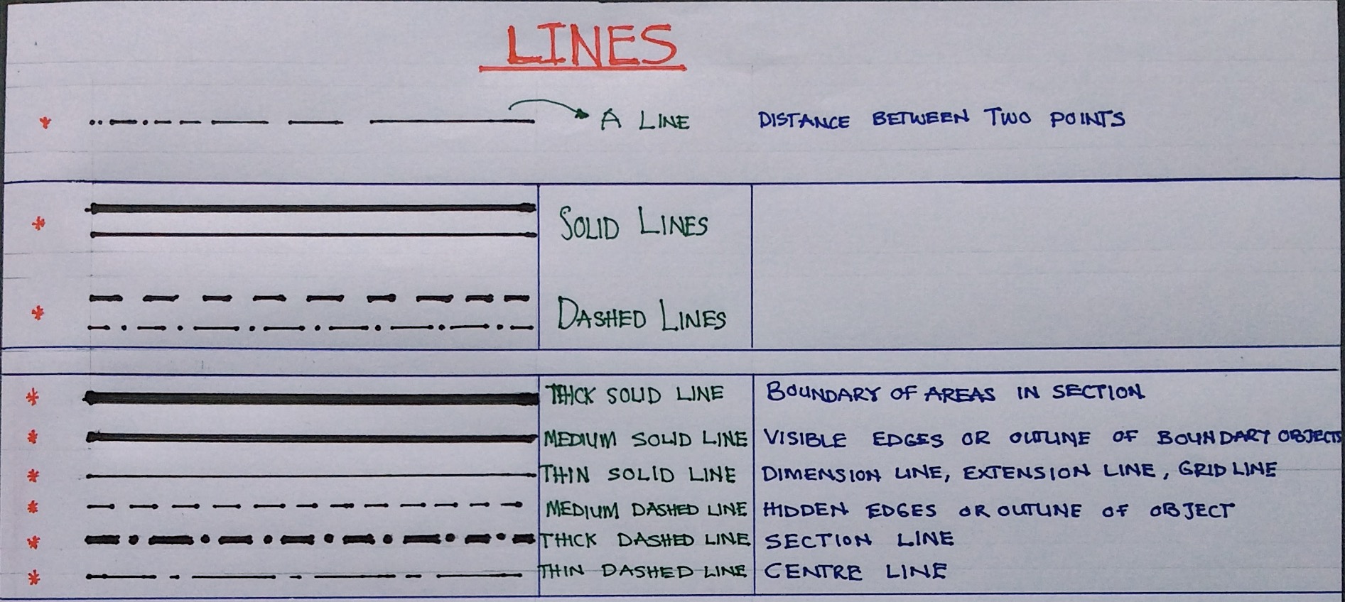
A line is a continuous point/dot. It can also be defined as the distance between two points. Every other element is made up of lines. They come together and form up drawings. Every line in a drawing has a specific meaning. In architecture, a combination of different line types and weights are used in communicating the meaning of each line.
Line Types
The two major types of line include solid lines and dashed lines. Solid lines are used in different weights or thicknesses to depict certain roles. Solid lines are majorly used to form the edge or boundary of a shape or plane. Dashed lines are used to indicate hidden elements. However, different pattern in dashed lines have different meanings.
Line Weight
The thickness of different line types has different meanings. Thin solid lines are used for construction lines, dimension lines, extension lines, grid lines etc. Thick solid lines are used to depict boundary lines, visible edges or outlines of building elements etc. Thin dashed lines (or chained lines) are used for hidden edges or outline of building elements, center lines etc., while thick dashed line or chained lines are used for section lines, property lines etc.
Symbols
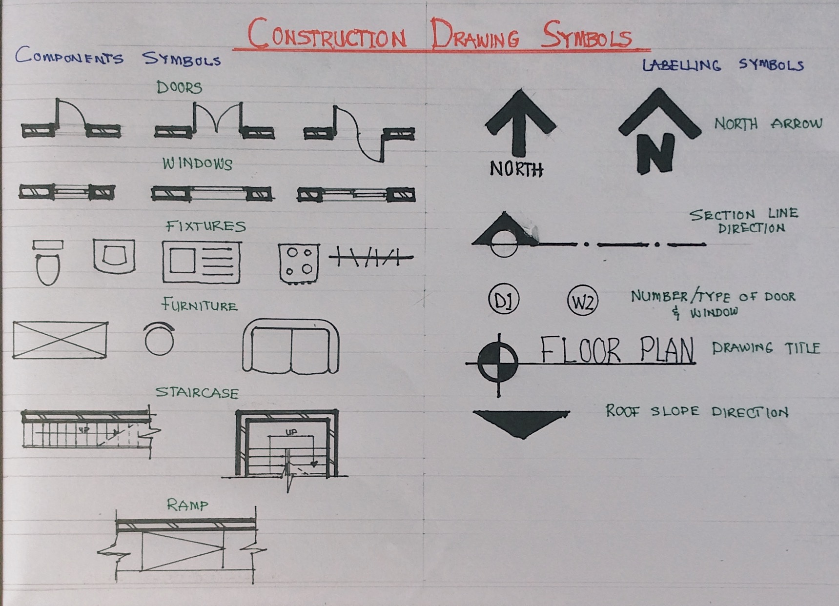
In the construction industry, nearly all professions have symbols that are unique to their line of work, for example, mechanical and electrical engineers have electrical symbols, plumbing symbols, fire alarm symbols, and heating, ventilation and air conditioning symbols. The architect, who is in charge or construction drawings, also has construction symbols which consist of component symbols and labelling symbols. Fig 2 is an example of some symbols used in architectural drawings.
Textures
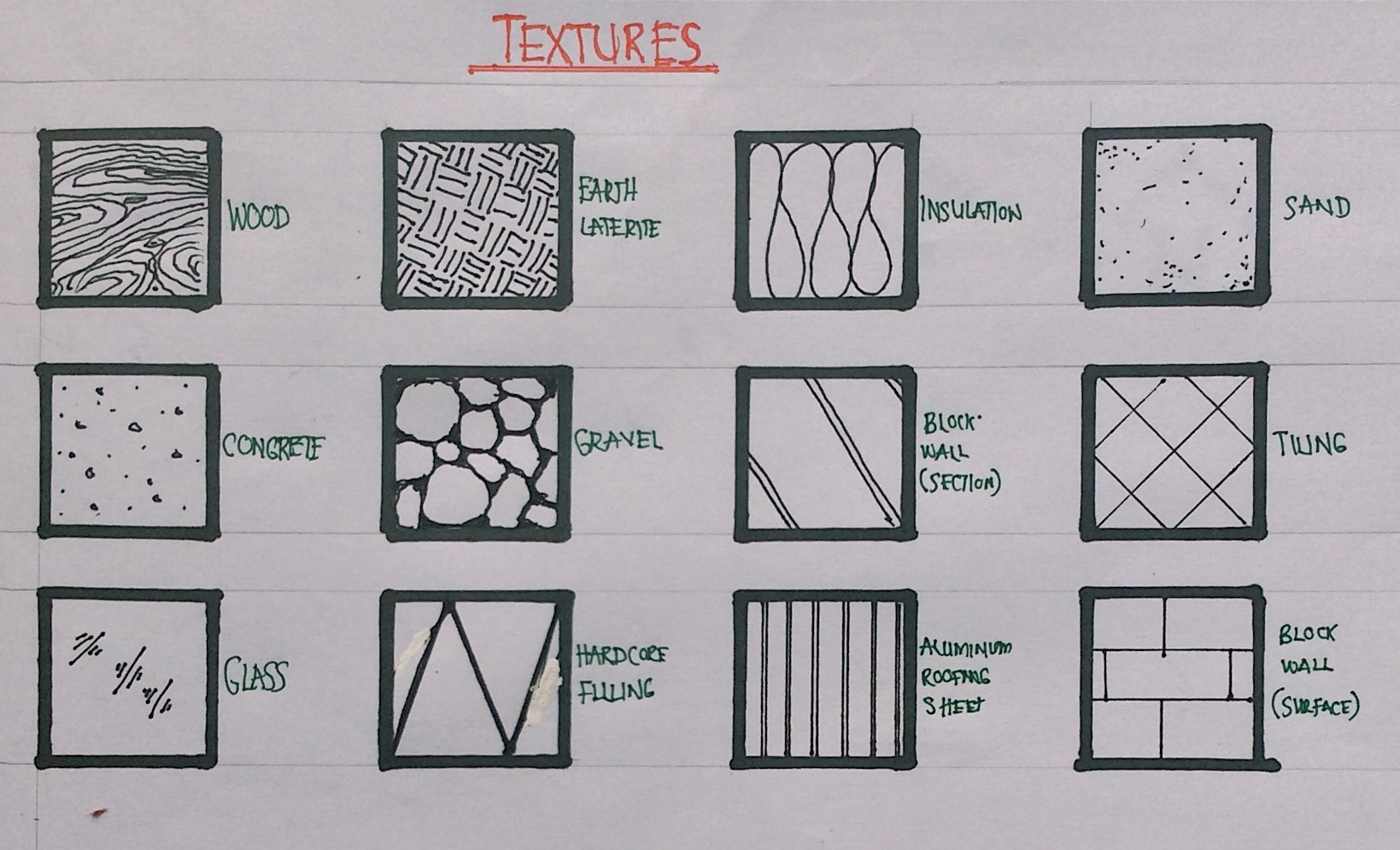
In addition to the previous elements, a drawing also needs to communicate different textures. These textures can be material either in section or surface view. The image below is an example of some textures used by architects in design.
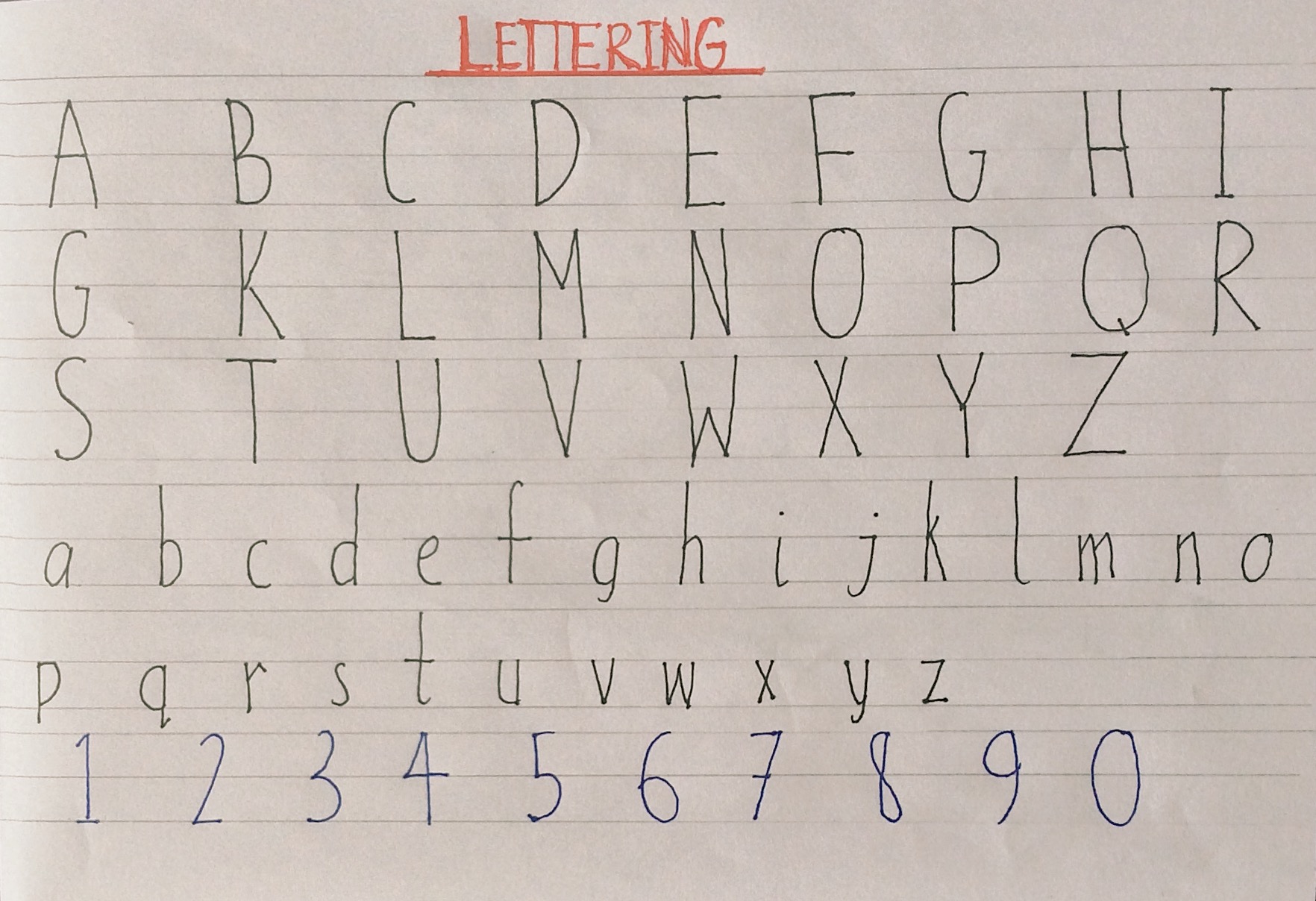
Lettering
Good lettering is also a vital part of architectural graphics. An architect is expected to have legible and neat lettering. Using thin lines as guides and appropriate fonts can help achieve good writing.
All these elements play side by side in helping the architect communicate his designs to other professionals. Consulting books like Architect’s Data, Architectural Graphic Standards, Design Drawing etc., will surely help in learning more about architectural graphics. Thank you for reading and stay tuned for the next episode!
Good it’s so educative, keep doing the good Jod
Awesome, great job Architect
Thank you!
Great write up twinnie. Keep up the good work 👏👏
Thank you!
Masha Allah.. Nice work keep it up
Thank you!
Your work is very nice and it’s understandable.
But I’ve been looking for space allocation, thanks
Check the post on space analysis or schedule of accommodation