The working drawing of a site plan gives various information. It tells us the size of the land, the exact location of a building on the land, the orientation of the site, and all necessary dimensions and specifications. In this post, you will learn about all the required information for the working drawing of a site plan.
The Site
A site is a piece of land where a building is located on. This land has a size, geographical location, topography, orientation and soil type. These are identified during site analysis. In the process of producing a working drawing of the site, the following must be indicated:
- The overall dimension of each side of the site.
- The beacon number of each corner of the site. (a beacon number is placed on all the points of a piece of land indicating its boundaries usually provided by local planning authorities)
- Bearings of the sides of the site.
- Contour lines showing the topography of the site.
- Direction of North.
- Name of access and adjacent roads.
- The size and swing of all gates including pedestrian.
- Levels of drains and discharge point of all drains.
The Building
The relationship between the building and the site it is situated on is one of the major uses of a site plan drawing. The building size, its orientation and setbacks are some key elements we can identify on a site plan. The following information about the building in relationship to the site must be indicated in working drawings:
- The overall dimension (on all sides) of all buildings located on site.
- The setback on all sides or to adjacent building(s).
- The location of entrances on each building.
- The name of the building(s).
- The finished ground floor level of buildings relative to an agreed datum.
Landscapes, Pavements and Other Features
The surrounding of a building within a site can tend to have landscaping elements, walkways, pavements, driveways, etc. All these elements need to be identified and fully described in the working drawing of a site plan. The following information must be indicated in the drawing:
- The finished levels of all pavements, driveways etc.
- The finishes of all pavements, driveways etc.
- The length and width of all pavements, driveways etc.
- The location and type of landscaping, foundations, sculptures with dimensions and number.
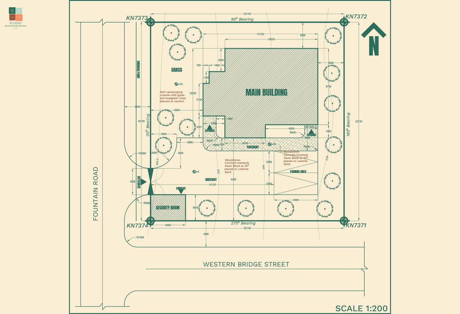
Graphics of Site Plan Working Drawing
- Scale
The size of a site plan in working drawings should be large enough to expose details of the drawing. The scale depends on the size of the drawing. 1:100 can be adopted for relatively smaller sites, while 1:200 can be adopted for larger sites. However, some parts of the site can be blown out with a bigger scale to reveal more information.
2. Dimensions
Dimensions are a vital part of working drawings. All parts of the drawing should be fully dimensioned; however, repetition should be avoided to prevent confusion. Dimensions should be accurate and legible.
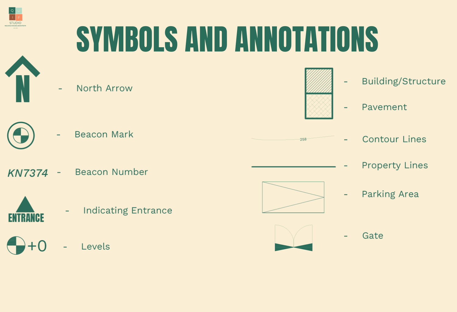
3. Symbols and Annotations
Working drawings are technical drawings therefore having many symbols and annotations for graphical representations. All symbols and annotations should be accurate and easy to understand by all members of the construction team. Here are some symbols and annotations used in site plan working drawings:
4. Specifications
Materials and finishing should be fully specified in the working drawing. This information can be provided in the drawing, or in the specification document of the project.
A site plan is helpful during the setting out of a project, therefore the information provided should be accurate and well described. To have a better view of a site plan working drawing and access to a complete checklist of information to be provided, you can click the download button below.
Thank you architect, we are really benefiting from your work
Thank you Usman.
It is indeed an educative write up not only to architects but rather to engineers as well. Keep the tempo warm. Kudos