The working drawing of a roof plan provides information about the roof and its elements. It provides us with the roof layout, materials to be used and the location of trusses and other roof elements. In this post, you will learn about the required information for the working drawing of a roof plan.
The information in a roof plan is categorized into the following:
Roofing Elements
- State roof trusses type and centres.
- Indicate position of spouts or rain water pipes.
- Indicate position of overhead tanks (if any).
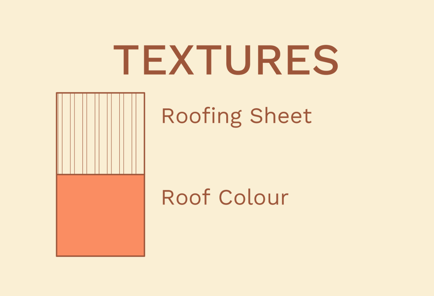
Roofing Materials and Finishes
- State type of roof covering.
- State materials for trusses and other roofing elements.
- State finishing to all concrete gutters.
Annotations and Other Elements
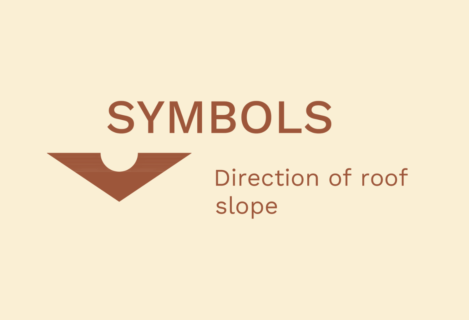
- Indicate fall of roofing sheets or screed.
- Indicate grid lines.
- Indicate section lines.
- Indicate dimensions of roof and roof elements.
Graphics of Roof Plan Working Drawing
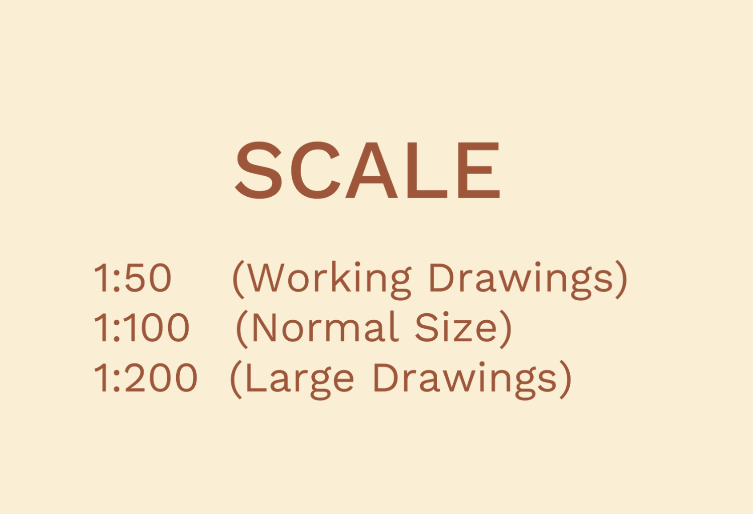
- Scale
Similar to the floor plan working drawing, the size of a roof plan in working drawings should be large enough to expose details of the drawing. 1:50 can be adopted for relatively smaller roofs, while 1:100 can be adopted for larger buildings. However, some parts of the roof plan can be blown out with a bigger scale to reveal more information.
- Dimensions
All parts of the drawing should be fully dimensioned; however, repetition should be avoided to prevent confusion. Dimensions should be accurate and legible.
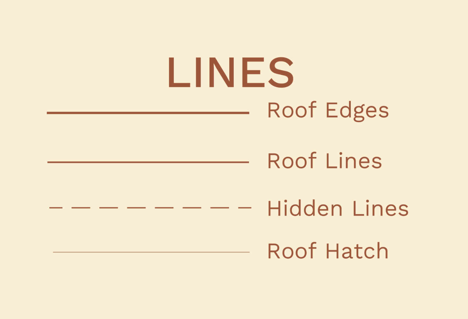
- Symbols and Annotations
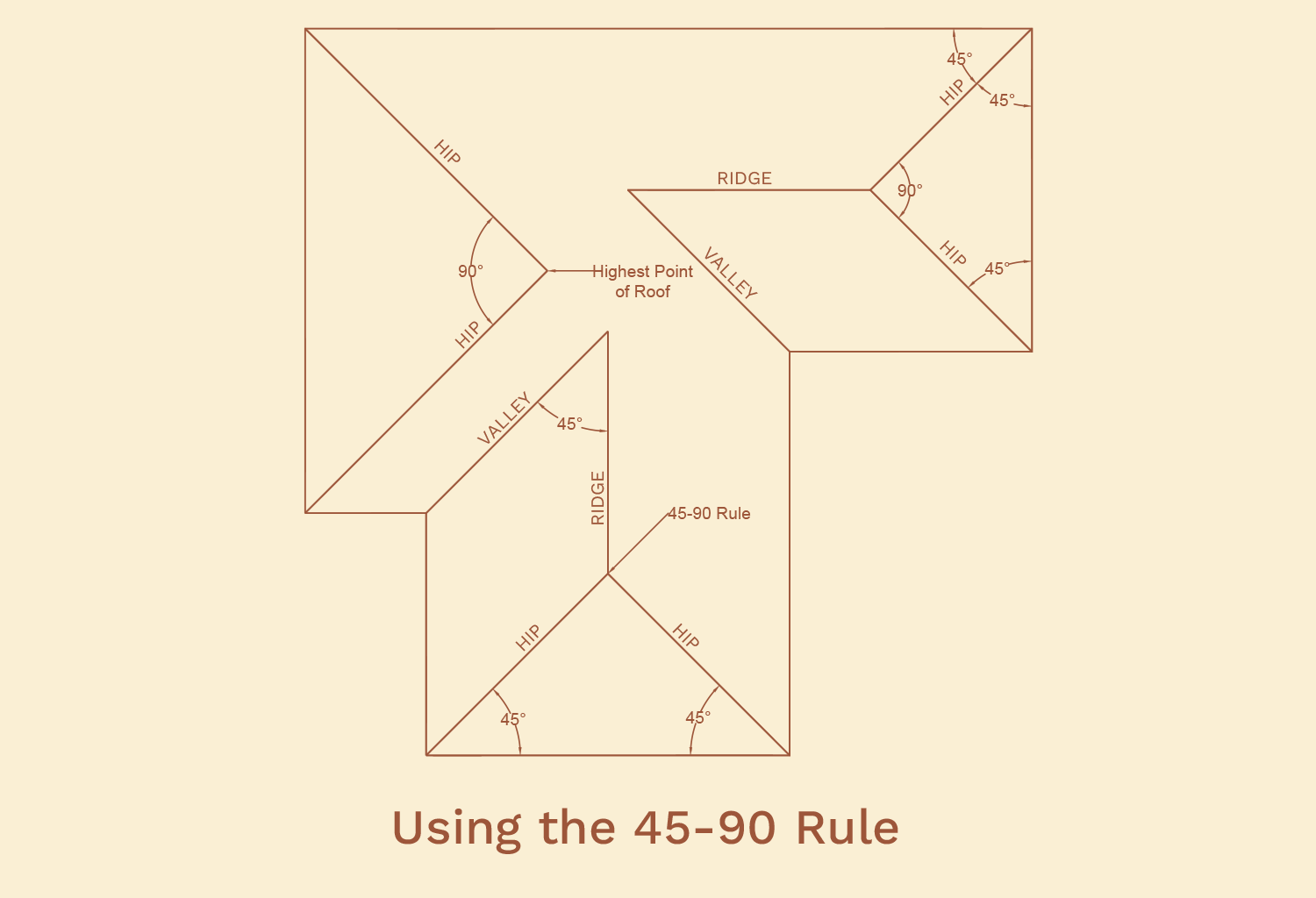
Here are some symbols and annotations used in roof plan working drawings:

- Specifications
Materials and finishing should be fully specified in the working drawing. This information can be provided in the drawing, or in the specification document of the project.
In conclusion, creating a roof plan is an indispensable skill in the field of architecture and design. This essential element not only adds the finishing touch to a building’s aesthetic appeal but also plays a pivotal role in ensuring structural integrity and weather protection. The detailed specifications and annotations within a roof plan serve as an invaluable guide, facilitating the realization of your architectural vision with precision and efficiency. As architects and designers, mastering the art of crafting roof plans is an essential step towards turning your creative concepts into tangible structures that stand the test of time.
To have access to a complete checklist of information to be provided, you can click the download button below: