The working drawings of a building’s various sections are an intricate puzzle of details, providing the vital blueprint for the construction process. Just as the floor plan working drawing unravels the spatial dimensions and design elements of a structure, section working drawings dive deep into the vertical dimension, offering an in-depth exploration of the building’s cross-sectional view. These drawings reveal the details of walls, openings, fixtures, staircases, and more, offering a comprehensive understanding of the structural components that shape a building’s form and function.
Much like the floor plan working drawing, section drawings also disclose the choice of materials and finishes employed, in addition to other graphical details that breathe life into the design. In this post, you will learn the information conveyed in section working drawings, while also gaining invaluable insights into their critical role in the construction of buildings.
Dimension and Sizes
- Dimension floor to ceiling.
- Dimension floor to lintel of doors and windows.
- Dimension floor to ceiling of windows.
- Dimension ceiling to lintel of windows.
- Dimension height of parapets
- Dimension risers, steps, half landing etc.
- Dimension thickness of slabs, pavement etc.
- Dimension height of ground floor above natural ground level.
- Dimension of balustrades, shelves, counters, worktops above floor levels.
Materials, Finishing and Levels
- Indicate level of all rooms through which section passes.
- Indicate floor finish of all rooms through which section passes.
- Indicate wall finish of all rooms through which section passes.
- State type of roofing sheets.
- State type of ceiling.
- State type of roof trusses (if further details are provided by other consultants, state so) and at what centers.
- State type of flashing to all walls.
- State finishing to concrete roof gutters.
- State type of skirting to all walls.
Opening and Fixtures
- Indicate width of all doors, windows and other openings.
- Indicate swings of all doors.
- Number all doors, windows and curtain walling etc.
- Locate all sanitary fittings and label them appropriately.
- Indicate position of all fixtures and label them appropriately.
Staircase and Ramps
- Width of all treads at staircases and all level changes.
- Number of all risers at staircases and all level changes.
- Indicate direction of flight at all staircases and all level changes.
- Indicate direction of the slope and the slope degrees/percentage.
- Indicate width of slope and all level changes.
Annotations and Additional Information
- Indicate functions of all rooms through which section passes.
- Provide grid lines.
- Indicate areas (if any) where further details are provided in subsequent drawings or by other consultants or manufacturers.
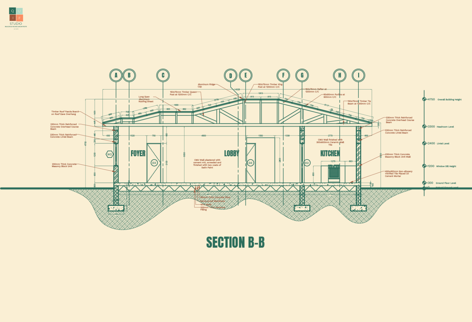
Graphics of Section Working Drawing
- Scale
The scale for a section working drawing, should be large enough to expose details of the drawing. 1:50 can be adopted for relatively smaller sections, while 1:100 can be adopted for larger buildings. However, it is necessary to blow out certain parts of the sectional drawing with a bigger scale to reveal more information.
- Dimensions
All parts of the drawing should be fully dimensioned; however, repetition should be avoided to prevent confusion. Dimensions should be accurate and legible.
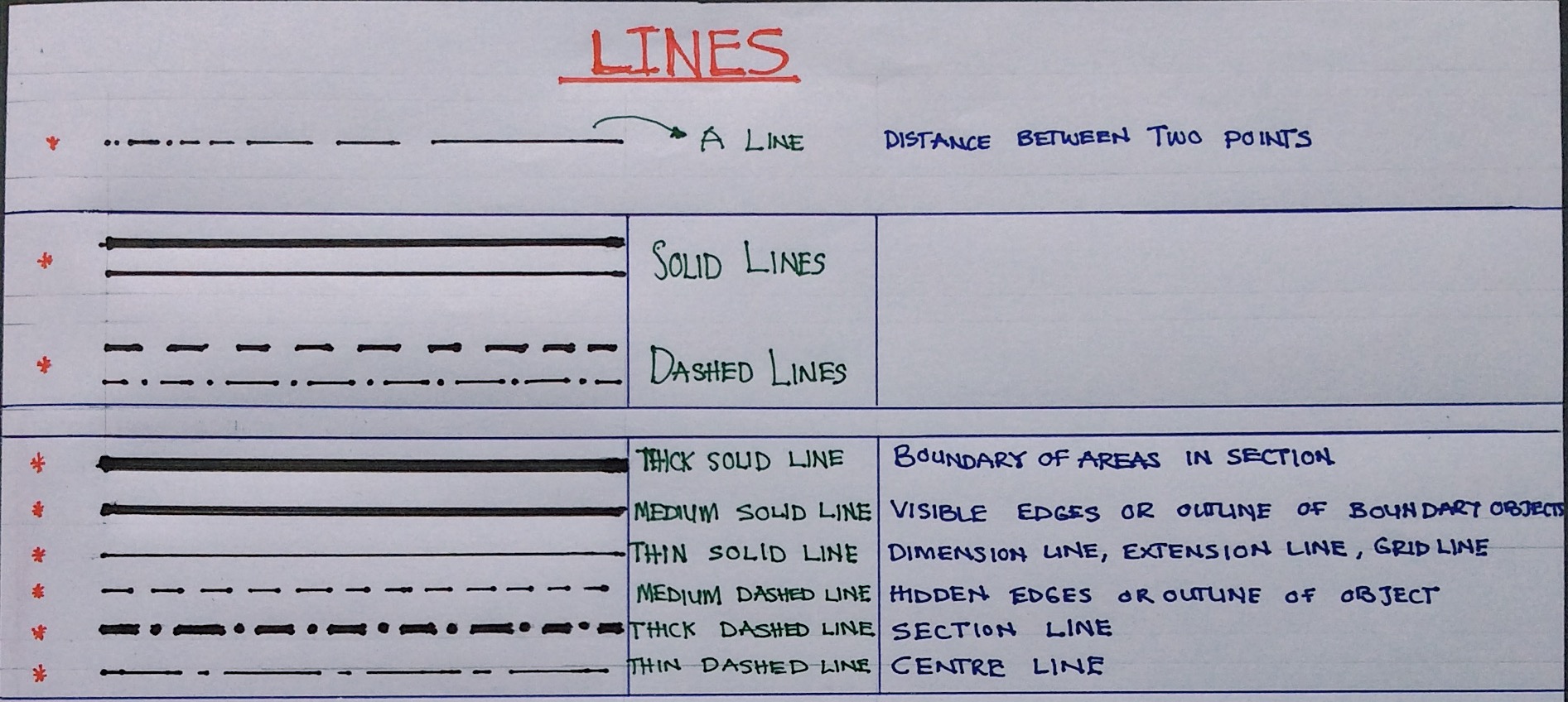
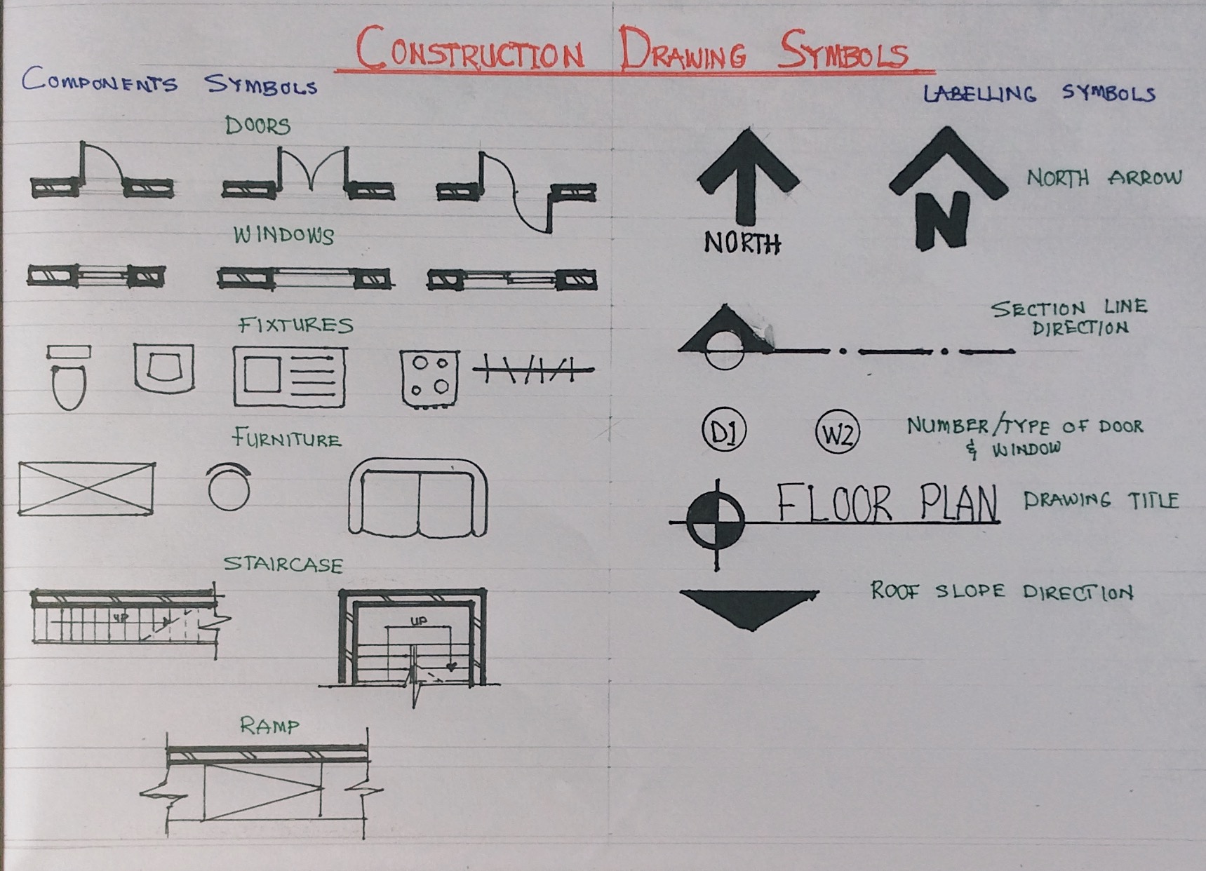
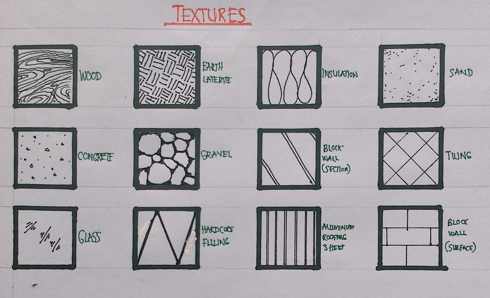
- Symbols and Annotations
Here are some symbols and annotations used in section working drawings:

- Specifications
Materials and finishing should be fully specified in the drawing. This information can be provided in the drawing, in schedules or in the specification document of the project.
Section working drawings are an essential part of the construction process, offering detailed insights into a building’s vertical aspects. They reveal the design elements, structural components, materials, and finishes crucial to transforming architectural vision into reality. Just as floor plan working drawings are vital for the horizontal layout, section drawings are indispensable for the vertical dimension.
To have access to a complete checklist of information to be provided, you can click the download button below: