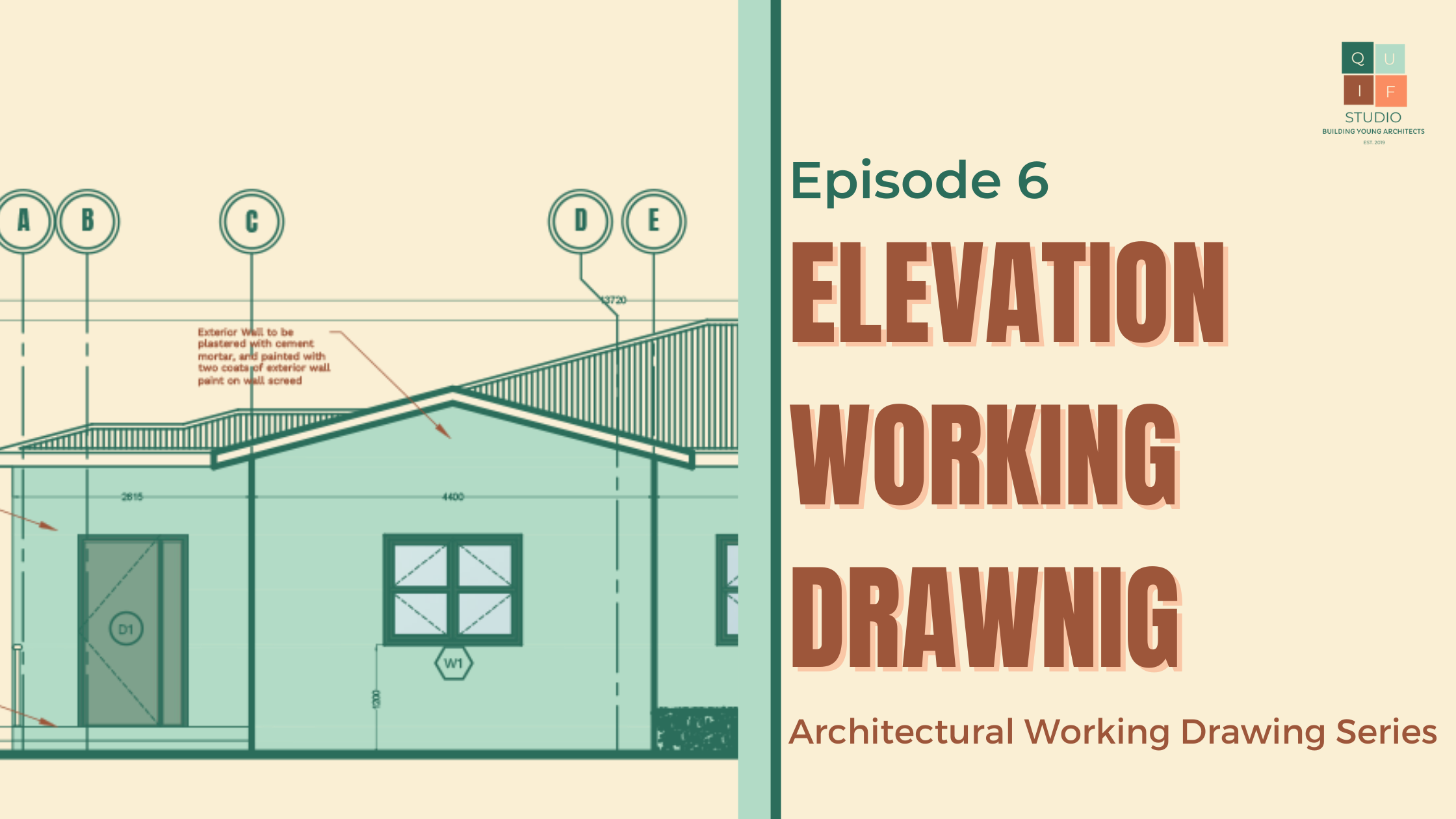
Elevation working drawings, like their counterparts in floor plans and section drawings, serve as an indispensable guide in the realm of architecture and construction. These drawings offer a vertical perspective on a building’s façade, encapsulating the very essence of its external appearance. Just as floor plans provide insight into the layout of a structure, section drawings unravel its inner workings, elevation working drawings reveal the outward face that meets the world. These drawings not only convey the aesthetic design elements but also provide critical information about materials, proportions, and architectural details.
In this post, you will learn the information conveyed in these drawings, while also gaining invaluable insights into their critical role in the construction of buildings. Given that most information has been covered in previous drawings, the required information for elevations are as follows:
Indicate levels of all floors, ceiling, parapet and assumed ground level.
Indicate finishing to all surfaces.
Indicate fixed and open-able parts of all doors and windows.
Dimensions and sizes of all façade elements.
Provide grid lines.
Indicate areas (if any) where further details are provided in subsequent drawings or by other consultants or manufacturers.
Graphics of Elevation Working Drawing
Scale
Similar to sections, the scale for an elevation working drawing, should be large enough to expose details of the drawing. 1:50 can be adopted for relatively smaller buildings, while 1:100 can be adopted for larger buildings. However, it is necessary to blow out certain parts of the elevational drawing to a bigger scale to reveal more information.
Dimensions
All parts of the drawing should be fully dimensioned; however, repetition should be avoided to prevent confusion. Dimensions should be accurate and legible.
Symbols and Annotations
Symbols and annotations can be adopted from previous drawings and used where necessary.
Specifications
Materials and finishings should be fully specified in the drawing. This information can be provided in the drawing, in schedules or in the specification document of the project.
Elevation working drawings are the visual blueprints of a building’s external charm. Offering insights into design elements and material choices, these drawings play a pivotal role in bridging architectural concepts with tangible structures. This post aimed to highlight their significance, empowering you to navigate the intricacies of elevational design with precision and flair.
To have access to a complete checklist of information to be provided, you can click the download button below:
The working drawings of a building’s various sections are an intricate puzzle of details, providing the vital blueprint for the construction process. Just as the floor plan working drawing unravels the spatial dimensions and design elements of a structure, section working drawings dive deep into the vertical dimension, offering an in-depth exploration of the building’s cross-sectional view. These drawings reveal the details of walls, openings, fixtures, staircases, and more, offering a comprehensive understanding of the structural components that shape a building’s form and function.
Much like the floor plan working drawing, section drawings also disclose the choice of materials and finishes employed, in addition to other graphical details that breathe life into the design. In this post, you will learn the information conveyed in section working drawings, while also gaining invaluable insights into their critical role in the construction of buildings.
Dimension and Sizes
Dimension floor to ceiling.
Dimension floor to lintel of doors and windows.
Dimension floor to ceiling of windows.
Dimension ceiling to lintel of windows.
Dimension height of parapets
Dimension risers, steps, half landing etc.
Dimension thickness of slabs, pavement etc.
Dimension height of ground floor above natural ground level.
Dimension of balustrades, shelves, counters, worktops above floor levels.
Materials, Finishing and Levels
Indicate level of all rooms through which section passes.
Indicate floor finish of all rooms through which section passes.
Indicate wall finish of all rooms through which section passes.
State type of roofing sheets.
State type of ceiling.
State type of roof trusses (if further details are provided by other consultants, state so) and at what centers.
State type of flashing to all walls.
State finishing to concrete roof gutters.
State type of skirting to all walls.
Opening and Fixtures
Indicate width of all doors, windows and other openings.
Indicate swings of all doors.
Number all doors, windows and curtain walling etc.
Locate all sanitary fittings and label them appropriately.
Indicate position of all fixtures and label them appropriately.
Staircase and Ramps
Width of all treads at staircases and all level changes.
Number of all risers at staircases and all level changes.
Indicate direction of flight at all staircases and all level changes.
Indicate direction of the slope and the slope degrees/percentage.
Indicate width of slope and all level changes.
Annotations and Additional Information
Indicate functions of all rooms through which section passes.
Provide grid lines.
Indicate areas (if any) where further details are provided in subsequent drawings or by other consultants or manufacturers.
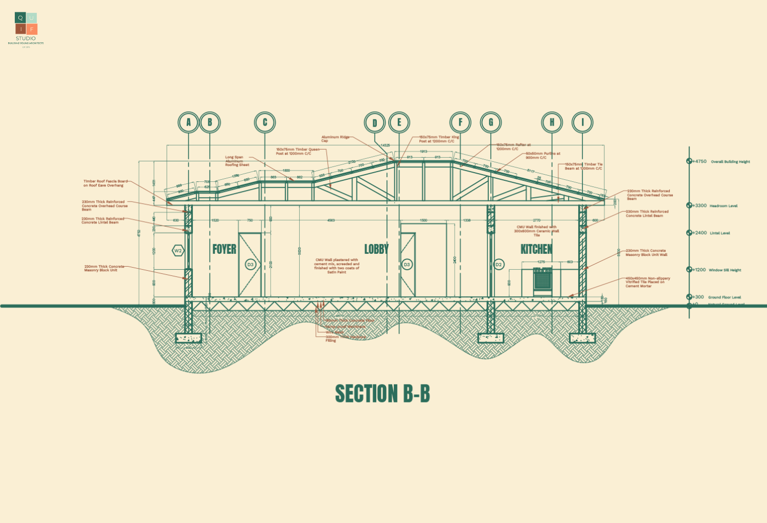
Graphics of Section Working Drawing
Scale
The scale for a section working drawing, should be large enough to expose details of the drawing. 1:50 can be adopted for relatively smaller sections, while 1:100 can be adopted for larger buildings. However, it is necessary to blow out certain parts of the sectional drawing with a bigger scale to reveal more information.
Dimensions
All parts of the drawing should be fully dimensioned; however, repetition should be avoided to prevent confusion. Dimensions should be accurate and legible.
Symbols and Annotations
Here are some symbols and annotations used in section working drawings:
Symbols and Annotations for Section Working Drawing
Specifications
Materials and finishing should be fully specified in the drawing. This information can be provided in the drawing, in schedules or in the specification document of the project.
Section working drawings are an essential part of the construction process, offering detailed insights into a building’s vertical aspects. They reveal the design elements, structural components, materials, and finishes crucial to transforming architectural vision into reality. Just as floor plan working drawings are vital for the horizontal layout, section drawings are indispensable for the vertical dimension.
To have access to a complete checklist of information to be provided, you can click the download button below:
Welcome to the launch of a new series called the Architectural Design Stage Series. This series is designed to cover architectural drawing, which is a major part of architectural design. This part of architectural design comes immediately afterPreliminary Design Stage. The information obtained and the decisions made during the preliminary design stage helps in designing site plans, creating floor plans, elevations and sections.
Throughout the course of the series, we will be discussing all the components that go into architectural drawing. Hence, the following is a list of upcoming episodes under this series:
Introduction to Graphic Communication
Understanding the Fundamentals of Design
Designing a Site Plan
Creating Floor Plans
Creating Roof Plans
Creating Sections
Creating Elevations
Perspectives
Stay tuned for this series and comment down below what your expectations are. If you are a student, tell us what your favorite step is, what your least favorite step is, where you think you are lacking the most, etc. I would really appreciate your feedback. You can also email me with any suggestions from my Contact page. This series will also run through Instagram so make sure you check out our page from the links below.
All spaces are designed to revolve around the human being. The design of spaces is derived from how the user interacts with his environment. The human body is a unique design on its own that works within a unique ratio and proportion, therefore, the design of the surrounding environment is inevitably planned to be functional and compatible with the user. Space analysis is a tool that helps architects assign measurements to proposed spaces in order to achieve functionality in design.
How are these measurements achieved?
Fig. 1 Basic Human Dimensions
These measurements are achieved by analyzing the space needed for basic and comfortable movement, the objects to be placed within the space, and how the user will interact with those objects. For example, in a bedroom, there will be movement from the entrance of the bedroom to the bed, closet/wardrobe, drawers, tables etc. There will also be movement from some objects to another, and movement caused by interacting with an object within the bedroom like using the closet, sitting at a table etc. Below is an example of some basic dimensions:
From these dimensions and the dimensions of furniture and fixtures, we are able to assign appropriate sizes to spaces in a building. All these dimensions and sizes are then later inputted into a document called Schedule of Accommodation.
A schedule of accommodation is a list of accommodation facilities and provisions required by the client or user of a building project. It is usually developed during the preliminary design stage by the architect. The preparation of a schedule of accommodation helps to determine the minimum space requirements for the building.
It may include:
Room reference number.
Room location (for example, building name / floor).
Room name.
Room type / description.
Room size (i.e. floor area, and sometimes dimensions, which may include height).
Number and type of occupants.
Relationships between rooms and groups of rooms.
Furniture, fixtures and equipment (FF&E) requirements.
Environmental conditions required (i.e. temperature range, humidity, air movement, acoustic conditions, lighting levels and so on).
Total areas.
Exclusions (such as circulation spaces).
Fig. 4 Bedroom Space Analysis
Fig. 4 shows the analysis of a bedroom space for one occupant. The minimum dimensions for a bedroom is 3m by 3.6m which is proven above using the basic spaces required for the user to interact with his/her space and the area of the furniture provided. These dimensions help in the planning of space more adequately.
Using these simple standards, the dimension of a space can easily be obtained by the architect. Thank you for reading and stay tuned!
Bubble diagrams are freehand diagrams made during the preliminary design stage to help plan or zone spaces with similar functions. The bubble diagram is the first step made towards achieving a floor plan. The information from a bubble diagram helps plan out major functions in a building, spaces in the building, their relationships, and sometimes even circulation patterns.
A functional flowchart is also a freehand diagram which is drawn after the bubble diagram to generate main functions or spaces in the building, how they connect to each other and circulation routes in the building. This is like a rough sketch of a floor plan. A very common mistake made when dealing with functional flowcharts is that students usually generate the flowchart after they have completed the floor plan, while the flowchart is supposed to be done before the floor plan.
There are some similarities between a bubble diagram and a functional flowchart. A simple google image search on bubble diagrams, you would realize that the bubble diagrams and functional flowcharts are practically the same thing. However, architecture education sometimes differs from various parts of the world, therefore, we have bubble diagrams and functional flowcharts which are two different things. The ideal chain of generating a floor plan starts with a bubble diagram, then a functional flowchart, and finally a rough sketch of the floor plan.
How to do a Bubble Diagram
A bubble diagram is derived from the main zones/functions in a building. These zones/functions are obtained from case studies and literature review. Their positioning is however based on information from site analysis and site zoning. Fig. 1 shows an example of site for a residential design. In the first diagram, the site has been analyzed and discovered to have major sources of noise from the roads around the site. This resulted in the zoning of the site showing the proposed area for development in the second diagram. The third diagram shows how the bubble diagram has been developed within the proposed development area. The public zone and service zone is placed close to the most accessible part of the site, while the private zone is placed away from it. A buffer zone is also provided as a barrier from neighboring sites.
Fig. 1: How to derive a Bubble Diagram
The zones in the bubble diagram are derived through case studies and literature review. The main functions in a house include living areas, sleeping areas and supporting functions like cooking areas. These areas are grouped into public zones, private zones and services as shown below in fig 2.
Fig. 2: Spaces within Zones
How to do a Functional Flowchart
A functional flowchart comes after the bubble diagram. This represents how spaces are connected with one another. This usually gives an idea of how a floor plan would look like. In a residential design, the main spaces include the living room, dining room, kitchen, storage room, bedrooms and toilets. There might be other spaces like a foyer, laundry room, a study, etc. but it all depends on the nature of the design brief. Like a flowchart, these spaces are represented in a diagram with lines connecting them. The lines serve as circulation routes through the buildings.
Fig. 3: Bubble Diagram and Functional Flowchart
Zones and spaces in bubble diagrams and functional flow charts are peculiar to the nature of a project. It is important to be creative with your diagrams. Nice sketches or details can be added to help make the diagrams more appealing or explanatory. For example, in the design of a hospital, the bubble diagram was made to represent some sort of microorganism under a microscope (Fig. 4). In the design of a 5-star hotel, the functional flowchart was in 3D diagram showing how spaces interact on different levels (Fig. 5).
Fig. 4: Bubble Diagram for HospitalFig. 5: Functionality Sheet for 5-Star Hotel
The significance of bubble diagrams and functional flowchart cannot be over emphasized. It is important that they are done before any sketches of the floor plan are made. (NOTE: My designs were done before the establishing of Quif Studio. These current blog posts are written in line with research, my experience and through consultations. Any mistakes, omissions etc. that have been noticed in my designs, were made a few years ago. The sole purpose of sharing them is to give an idea of what each and every step should look like)
Site analysis is the process of analyzing the existing context of a proposed site which includes the climate, geography, history, and infrastructure of the site. The purpose of a site analysis is not only to be familiar with the above factors, but also it determines the starting point for the development of the actual design ideas and concepts. That simply means that the majority of the subsequent steps in the preliminary design stage are based on the information obtained from site analysis.
Site analysis is usually presented in a diagrammatic format where all the features of the site are discussed or represented by a sketch. This can usually stretch to 5 sheets or more, depending on the level of details that are required. The features that are mostly … are discussed below:
An Example of Site Analysis An Example of Site Analysis
Climatic and Geographical Features
These are the largest features discussed under site analysis as they form majority of the physical features of the site. Below is a list of items which fall under these features:
1. PREVAILING WINDS (Trade Winds)
Direction.
Maximum, minimum and average velocities.
Special forces e.g storm, tornado, hurricane
2. SOLAR ORIENTATION
Sun angles
Days of sunlight
Cloud cover
Shading of or from adjacent structures, natural features and vegetation.
3. TEMPERATURE
Ranges of variation.
Maximums and minimums.
4. HUMIDITY
Ranges of variation.
Maximums and minimums.
5. PRECIPITATION
Peak period tables.
Annual and seasonal totals.
6. TOPOGRAPHY
Legal property description, including limits of property, easement, rights of way and north indication.
Topographic maps and aerial photos.
Slopes: percentage, aspect and orientation
Erosion channels.
Extent, location and general configuration of rocks, ledges, ridges, drainage, and some other unique features.
Visual characteristics.
Potential problem areas during construction.
Analysis of physical features and their relationships within, into and off the site.
Existing access and circulation; vehicular and pedestrian.
Vegetation.
Existing water bodies: Location, size, depth and direction of flow.
Water quality: Clean, polluted, anaerobic conditions etc.
Basic surface soil: sand, clay, silt, rock, gravel, loam, limestone etc.
Rock and soil type: character, formation and origin, geologic formation process and parent material.
Inclination.
Bearing capacity.
Bedrock: depth to bedrock and classification.
Environment hazards.
Historical and Infrastructural Features
These are features that deal with the history of the site, what it was previously used for and the site’s infrastructure, which is mostly dealing with existing infrastructure on and off the site, or the proximity to off site infrastructure. Below is a list of items that fall under these features:
1. UTILITIES
Portable water.
Electricity
Sanitary sewer service.
Storm drainage (surface and subsurface)
2. IMMEDIATE SURROUNDINGS
Neighboring structures: buildings, satellites, dishes etc.
Shading and solar access
Noise from streets, emergency services, aircraft etc.
Odours
Views and Vistas
3. GENERAL SERVICES
Fire and police protection.
Hospitals/clinics
Trash/refuse removal services.
Electricity services.
Site analysis usually goes hand in hand with site zoning which will be the next episode. It gives a better understanding of the information obtained during site analysis. A good site analysis is based on a comprehensive site visit. All these details can only be obtained through a proper site visit. I hope this post gives you a better understanding on site analysis and why it fell into The 3 Most Neglected Steps in Design.
Thank you for reading and stay tuned for the next episode!
(NOTE: My designs were done before the establishing of Quif Studio. These current blog posts are written in line with research, my experience and through consultations. Any mistakes, omissions etc. that have been noticed in my designs, were made a few years ago. The sole purpose of sharing them is to give you an idea of what each and every step should look like)
Welcome to the launch of a new series called the Preliminary Design Stage Series. I know from the title, you might be thinking “what is going on here?“. Well today, I am officially launching this series for the sole purpose of explaining what the entire preliminary design stage entails. Throughout the course of the series, I will be talking about each preliminary step taken before any architectural design.
From my previous post, which was talking about The Most Neglected Steps in Design, I pointed out that the most neglected steps are mainly from the preliminary stage which usually end up having an adverse effect on the overall design. This series is to help guide anyone in the architectural world (both in training and in practice) on what the steps are, their importance, and how to do them properly.
What is Preliminary Design Stage?
From the word preliminary, this is a stage in design that is done before the actual 2D or 3D architectural drawings. The stage involves gathering information of the site, its surroundings and the building type to be built or designed, and how that information is used in producing a functional design that will satisfy the users and fit perfectly into the environment. In a more detailed list below, these are the items that fall under the preliminary stage:
Introduction
Case studies and literature review
Site selection criteria
Site maps (site location map, vicinity map, etc)
Site analysis
Site zoning
Space analysis
Bubble diagrams
Functional flow charts
Schedule of accommodation
Design concept
Depending on the project given, you might end up having a wider range of steps. For example, there might be cases where you are including sustainability or energy solutions to your design; sheets or presentations will be required on those issues which fall under the preliminary steps. In some cases, you are required to give an explanation of your building system, the materials and construction. This is also part of the steps. I only captured these 11 steps because they are the basic ones, but some of them are so wide and have a lot of categories under them as well.
Stay tuned for this series and comment down below what your expectations are. If you are a student, tell us what your favourite step is, what your least favourite step is, where you think you are lacking the most, etc. I would really appreciate your feedback. You can also email me with any suggestions from my Contact page. This series will also run through Instagram so make sure you check out our page from the links below.
When anyone hears the word “architecture” or “architect”, only one word comes to mind. That word is design. The primary function of an architect is to design, and as we all know there are many stages that are taken in the design process before the final product is achieved (2D drawings, 3D drawings, models). In the preliminary stages of any architectural design, there are many things to consider like the site selection criteria, site location, orientation, concept development, zoning, bubble diagrams, space analysis and many more. There is also the specification stage where materials, finishing and construction methods are chosen. All these come together to form the lines drawn on paper (plans, elevations, sections) which will later on become a reality (building/structure). Neglecting any of these steps will have a drastic effect on any design or building. Today, I am going to highlight the 3 most neglected steps in design which are:
Site Analysis
Site Zoning
Specification writing and Detailing
Site Analysis
In the early stages of my training, I used to spend hours making sheets on site analysis and site zoning. I would make them as colorful as possible and draw many diagrams, but the truth was I did not know what half of those things meant. When I was presenting my drawings, I would just say “this is my site analysis showing the analysis of the site”. Thinking of it now makes me laugh honestly because that was just dumb, but towards my final year after doing much reading and going through courses like building climatology, I came to realize what those diagrams actually meant. I even challenged myself into choosing more complex sites as I reached my final year because I knew I could analyze them the right way and make designs that can fit right into the sites. So, how do you do a site analysis the right way? Below is a short guide on how to do a proper site analysis:
Site analysis is done to analyze the existing features of any given site. It has 4 categories which are the geographical features, infrastructural features, climate features and vicinity features.
All categories are to be described in detail. For example, geographical features include the sun path, trade wind directions, orientation, soil type, topography, vegetation, etc. you are to describe each of these in correspondence with your site of choice. These details might vary from different sites, therefore you and your friend using different sites may not have the same description.
It is important to visit your site of choice to help you get more information about the site vicinity and existing infrastructure. For example, google map might show you the structures surrounding the site and those existing on it, but it surely will not give you any source of noise, footpaths, the main direction of wind, etc.
As a student, you can create separate sheets dedicated to each category which will enhance the credibility of your work, while in practice you can explain the value of site visitation and its importance towards producing a better design for the client.
Source: Pinterest
Site Zoning
This is one the easiest yet most neglected steps in design. Zoning is all about knowing where to position certain spaces in a design based on some features that might affect the functionality of the space. These features are accessibility, noise, privacy, and security. Traditionally in training, we draw the shape of the site, include existing roads, and then zone them into 3 parts e.g. most accessible, semi accessible and less accessible, but there is much more to that when it comes to zoning. Zoning falls hand in hand with your bubble diagram. The application of these falls under of two types. There can be a site zoning or site bubble diagram and there is the zoning or bubble diagram for your building. Both are important but they are not the same. The zoning of your site will surely affect the zoning of the main building. For example, a nearby factory may affect your site zoning, which will may result in the positioning of some facilities (e.g. parking) in a certain way. Those facilities may not affect the zoning of your building as parking areas may generate unwanted noise. It is important to pay attention to these details as they can make or break your design.
Source: Pinterest
Specification writing and detailing
I had to reach my final year before I learnt how to make details on my own. Yes, I admit it. It was one of the things I hated doing the most as a student, and if not for a course I took a few months ago during my first year in my master’s program, I think I would have hated it for life. Besides, what is the point of making details? I have never seen a drawing submitted to a client with details and those details being used during construction. What made me realize how important detailing and specification is, was a statement my lecturer once made. He said “What do think made Zaha Hadid or Norman Foster or Frank Gehry the best? Was it because they opened their construction textbooks and copied their roofing details or wall details? Or was it because they studied the existing ones carefully and built on them?”. He explained that details are creations of our own 3D imagination. It tells us how we want a certain member to look like and how that look would be achieved. Sure there are members that are likely to be the same in every design, for example, foundation footing or roof trusses, but sometimes these members can be fabricated to fulfill a certain purpose like insulation, finishing etc.
Source: Pinterest
Specification writing and detailing go hand in hand as you need to specify the materials to be used and how they are going to be used. Lack of specification usually results in wrong choice of materials by someone who might not even have any knowledge of the matter. The wrong type of tiling in a bathroom can result to a person slipping which may lead to serious injury or even death. A simple tip for students on learning specification is to familiar with the materials around you. Know what type of flooring you are walking on, learn how it is made or fabricated, learn whether it is the best option for that specific location, and always ask questions.
It is particularly important to ensure you get all these things right because they highly affect the construction method, choice of materials and even the design as a whole. These are not only neglected by students, but it is quite common to see existing buildings around you that possess various problems not only as a structure but also affects the users of that building. Once the user is not satisfied, the building is considered to be poorly designed.
Thank you for reading, subscribe to my blog and stay tuned for more posts!