Detailing or details in architectural working drawings are like the secret sauce in a recipe – they might be subtle, but they make all the difference. These specifics go beyond the big picture, giving character to each nook and cranny of a building, turning a concept into a reality you can touch. In this post, we will go over why details are important and how to do them properly.
What are Details?
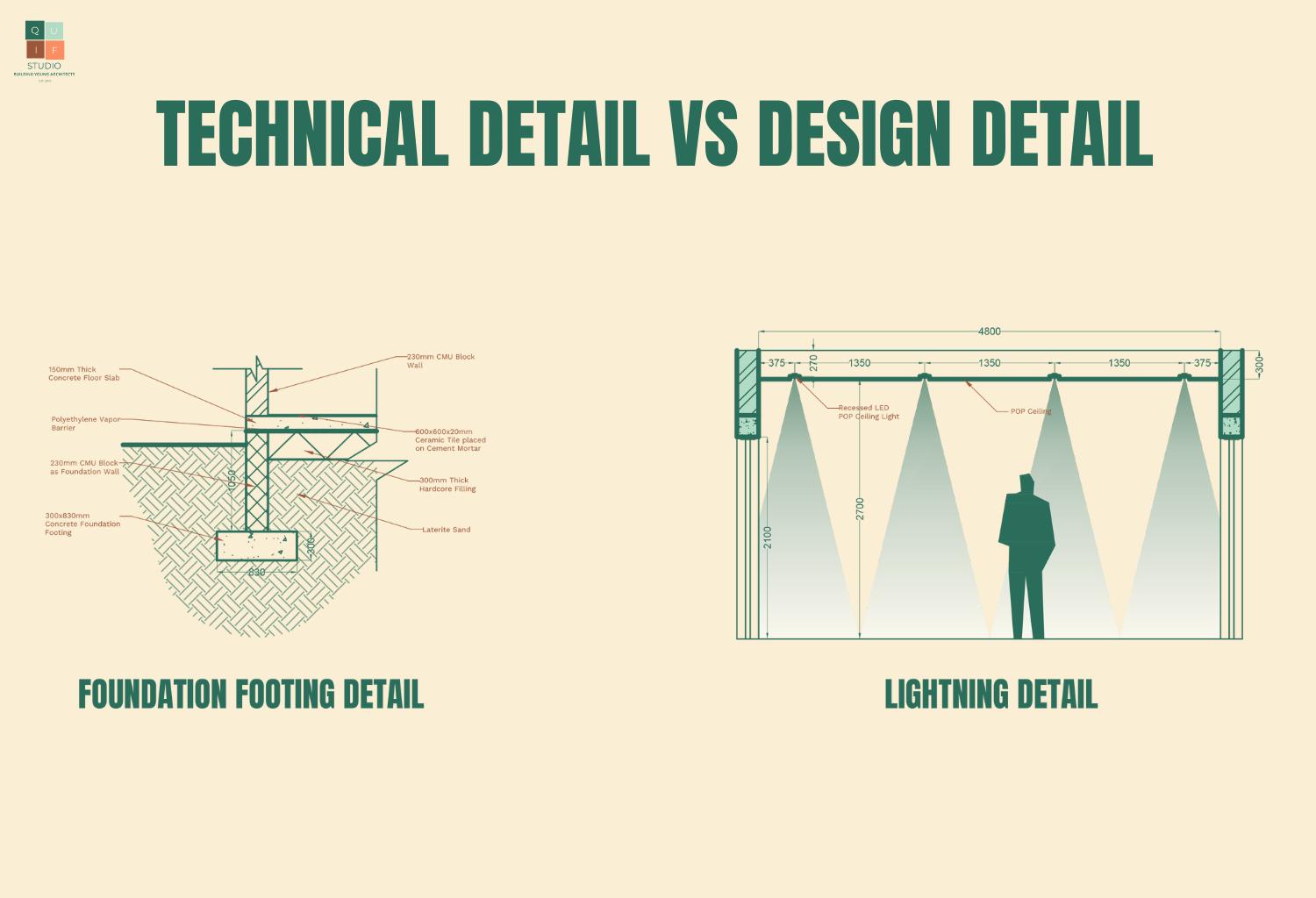
Simply put, details are drawings that show the assembly of building components. They show how parts are connected and how they interact with each other. These drawings are done to provided detail information of building components which allow them to be built in real-time. Details can either show technical details which are mainly construction related or design details which show aesthetic elements in a building.
Why are Details important?
- Proper details allow for a smoother construction process.
- Details allow a more detailed description of the scope of work. They allow for precise bidding which can save money in the long run.
- They give the ability to control the quality of a project and ensure the final result is exactly as envisioned by the architect.
- They ensure clear communication between the architect and the contractor.
- Well-detailed buildings lead to a sense of thoughtful design that gives an air of quality to a project.
- The time and care invested up-front in the process through details lead to fewer issues with maintenance and renovations long-term.
Important Areas for Details
Here are some key areas that require details:
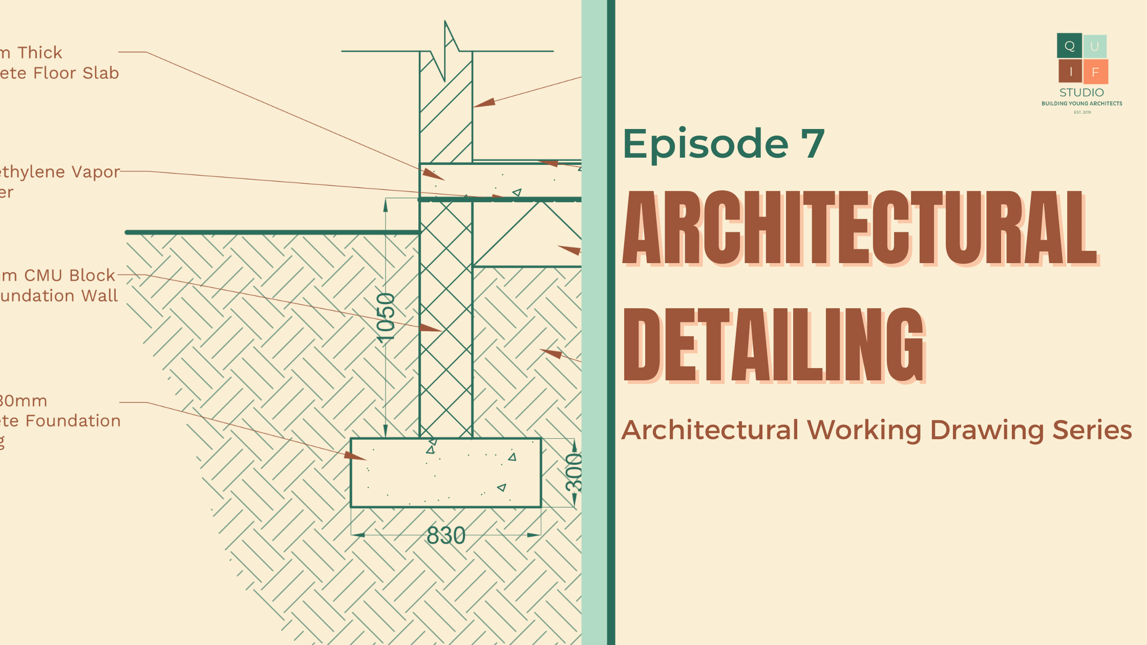
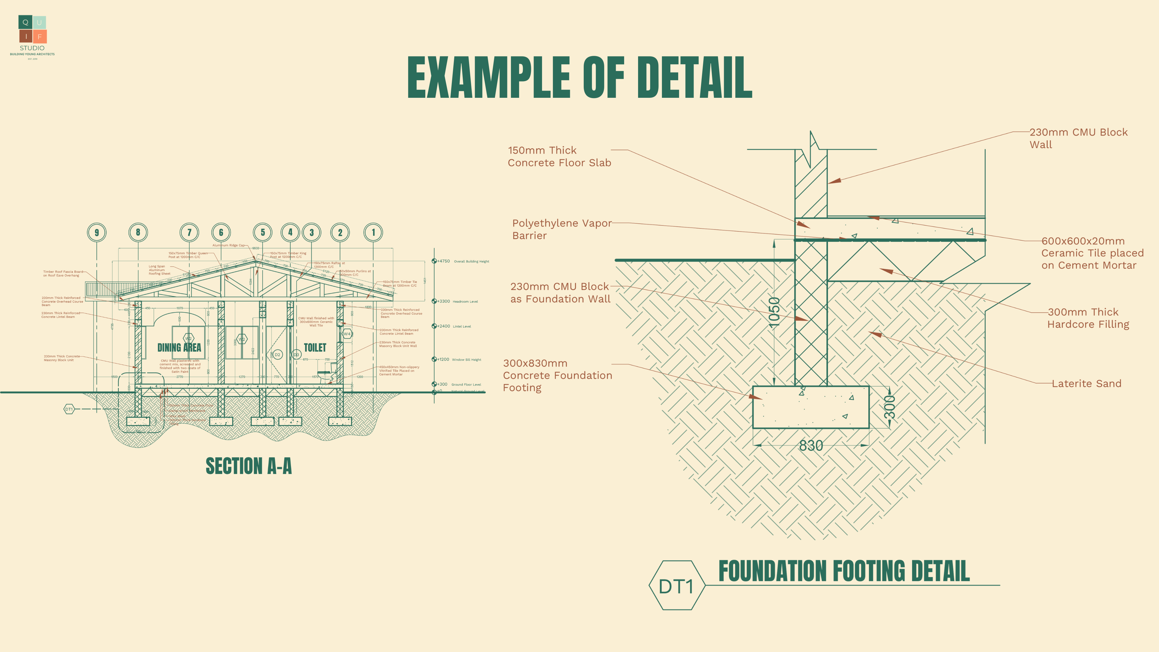
- Structural Elements: From the roots of the building to its highest branches, details here keep everything standing tall and strong. Examples of this can be foundation footings, Damp-proof Membrane Course (DPC), beam to column joints, etc.
- Facades and Finishes: This is where the aesthetics come into play. The details of materials and finishes can turn a drawing into a visual masterpiece. Examples include wall panel details, cladding details, tile skirting details, etc.
- Doors and Windows: Imagine doors that don’t quite fit or windows that won’t open – details here make sure everything works as it should. Examples include window sill details, door hinge details, etc.
- Stairs and Ramps: Here, dimensions and specifications ensure safe and stylish ways to move around the building.
- Roof Structures: From the rafters to the fascia, details guarantee a roof that not only keeps the rain out but looks good doing it. Examples include rafter details, roof eave details, roof ridge details, gutter details, etc.
Elements of Details
In drawing details, here are the major elements that can be seen in the drawing:
- Scale
The purpose of details is to expose how building components interact and how they can be assembled, therefore, they should be drawn in a scale that allows for those components to be visible. Larger scales are required for details. The scales can range from 1:25, 1:20, or 1:10.
- Dimensions
The sizes of all the detail components should be properly indicated to ensure proper communication.
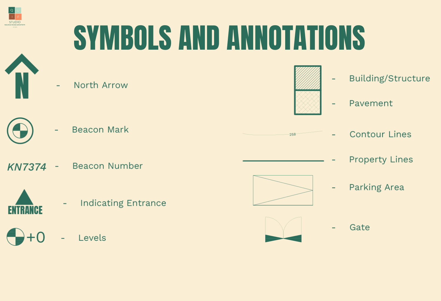
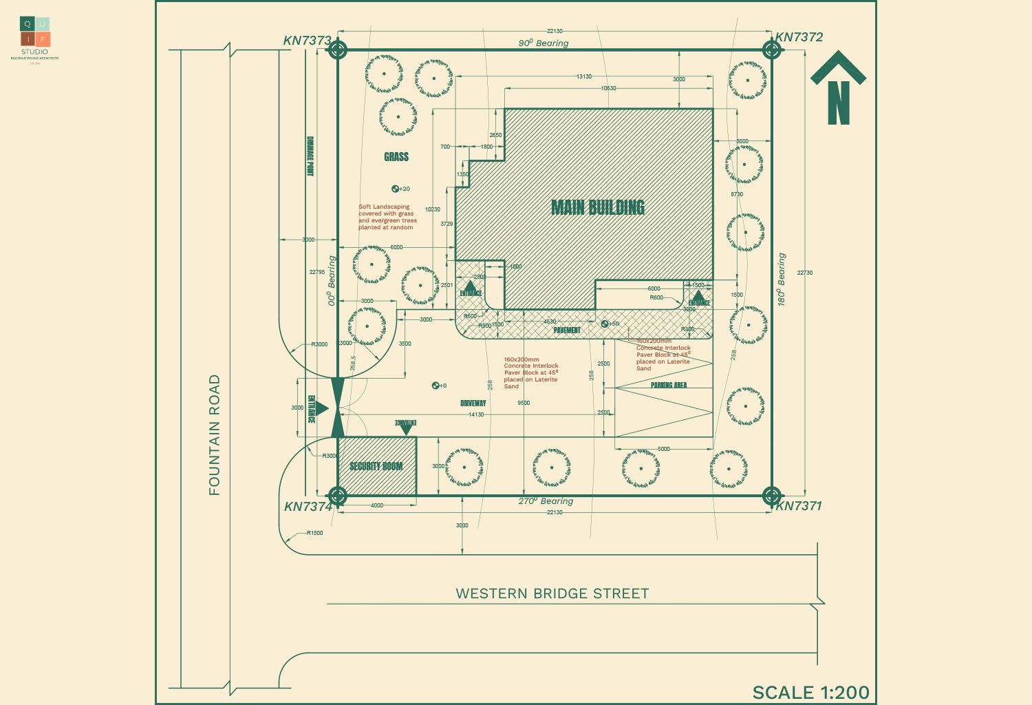
- Symbols and Annotations
Proper symbols and annotations should be used when drawing details. Materials should be indicated in their appropriate
- Specifications
The building components should be properly specified in detail drawings. The specification should include the material and how it may interact or be connected with another material.
You should ensure to indicate the location of any detail that you choose to draw in the appropriate drawing.
Conclusions
In conclusion, architectural detailing serves as the cornerstone of a building’s charm and functionality. Much like a well-crafted story, these details weave together to define the visual and structural character of a structure. This blog post aimed to underscore the significance of paying attention to architectural detailing, empowering you to enhance your designs and create spaces that not only meet practical needs but also captivate with their unique aesthetic flair. Armed with a focus on these details, don’t be afraid of drawing details, you’re now better equipped to elevate your architectural endeavors with precision and style.